


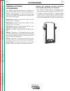
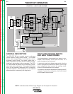
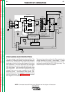

PRECHARGE AND PROTECTION
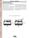
The input voltage is rectified by the input rectifier. The
resultant DC voltage is applied, through the reconnect
switch, to the power board. The power board contains
precharging circuitry for the safe charging of the input
filter capacitors. Once the capacitors are precharged
and balanced the control board activates the CR1+
CR2 input relays. This connects full input power to the
filter capacitors. When the filter capacitors are fully
charged they act as power supplies for the IGBT
switching circuit. The Insulated Gate Bipolar Tran-
sistors supply the main transformer primary winding
with DC current flow. See IGBT Operation discussion
and diagrams in this section.
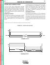
The power board also monitors the filter capacitors for
voltage balance and under or overvoltage. If either
should occur, the appropriate signal is sent to the con-
trol board to deactivate the CR1+ CR2 input relay. The
machine output will also be disabled.
THEORY OF OPERATION
E-3 E-3
PRO-CUT 80
Return to Section TOC Return to Section TOC Return to Section TOC Return to Section TOC
Return to Master TOC Return to Master TOC Return to Master TOC Return to Master TOC
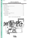
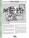
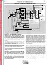
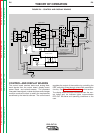
NOTE: Unshaded areas of Block Logic Diagram are the subject of discussion.
INPUT
LINE
SWITCH
INPUT
RECTIFIER
FAN
MOTOR
"A"
L
E
A
D
AUXILIARY
TRANSFORMER
OUTPUT
CONTROL
AIR
PRESSURE
SWITCH
P
R
O
T
E
C
T
O
N
I
SIGNAL
CR 1
DRIVE
SIGNAL
RELAY
IGBT
GATE
SIGNALS
R
E
A
D
Y
A
I
R
L
O
W
T
H
E
R
M
A
L
S
A
F
E
Y
T
TRIGGER & SAFETY
ELECTRODE & TRANSFER
CURRENT FEEDBACK
PILOT ENABLE
ELECTRODE SOLENOID ENABLE
AIR SOLENOID ENABLE
AIR
SOLENOID
TRIGGER & SAFETY
E
L
E
C
T
R
O
D
E
S
O
L
E
N
O
I
D
TORCH
CONNECTOR
ELECTRODE
NOZZLE
WORK
R
E
C
O
N
N
E
C
T
S
W
T
C
H
I
POWER BOARD
CR 1
RELAY
IGBT
IGBT
IGBT
IGBT
CAPACITOR
CAPACITOR
CURRENT
TRANSFORMER
CONTROL BOARD
DISPLAY BOARD
18/36VAC
12VAC
24VAC
MAIN
TRANSFORMER
OUTPUT BOARD
CHOKE
PILOT
TRANSISTOR
THERMOSTATS
115VAC
REMOTE
INTERFACE
RECEPTACLE
&
2
& 2