


Return to Section TOC Return to Section TOC Return to Section TOC Return to Section TOC
Return to Master TOC Return to Master TOC Return to Master TOC Return to Master TOC
TROUBLESHOOTING & REPAIR
F-17 F-17
PRO-CUT 80
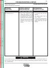
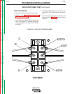
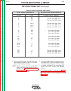
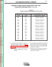
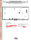
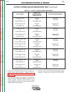
PRIMARY POWER BOARD RESISTANCE TEST AND
CAPACITOR VOLTAGE TEST (continued)
TEST POINT TERMINALS ANALOG METER X10 RANGE
+ Probe - Probe Acceptable Meter Readings
201 207A Greater than 1000 ohms
207A 201 Less than 100 ohms
204 207A Greater than 1000 ohms
207A 204 Less than 100 ohms
202A 204 Greater than 1000 ohms
204 202A Less than 100 ohms
202A 201 Greater than 1000 ohms
201 202A Less than 100 ohms
205 203A Greater than 1000 ohms
203A 205 Less than 100 ohms
208 203A Greater than 1000 ohms
203A 208 Less than 100 ohms
206 208 Greater than 1000 ohms
208 206 Less than 100 ohms
206 205 Greater than 1000 ohms
205 206 Less than 100 ohms
TABLE F.2
PRIMARY POWER BOARD RESISTANCE TEST POINTS
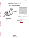
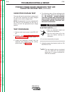
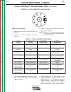
6. If the power board does not meet the
acceptable readings outlined in Table F.2,
the board is faulty. Replace. See Power
Board Removal and Replacement
Procedure.
NOTE: Complete power board and filter
capacitor replacement is recom-
mended.
7. If the power board “passes” the resistance
test, the IGBT portion of the board is good.
However, other circuits on the power board
may be faulty. These circuits are NOT readi-
ly tested or serviceable.
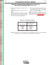
8. Carefully reconnect leads #201, #204, #205,
and #208 to their appropriate terminals.
Torque To 75 IN. LBS.