


Return to Section TOC Return to Section TOC Return to Section TOC Return to Section TOC
Return to Master TOC Return to Master TOC Return to Master TOC Return to Master TOC
TROUBLESHOOTING & REPAIR
F-39 F-39
PRO-CUT 80
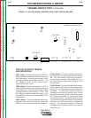
LOW VOLTAGE CIRCUIT TEST (continued)
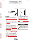
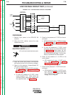
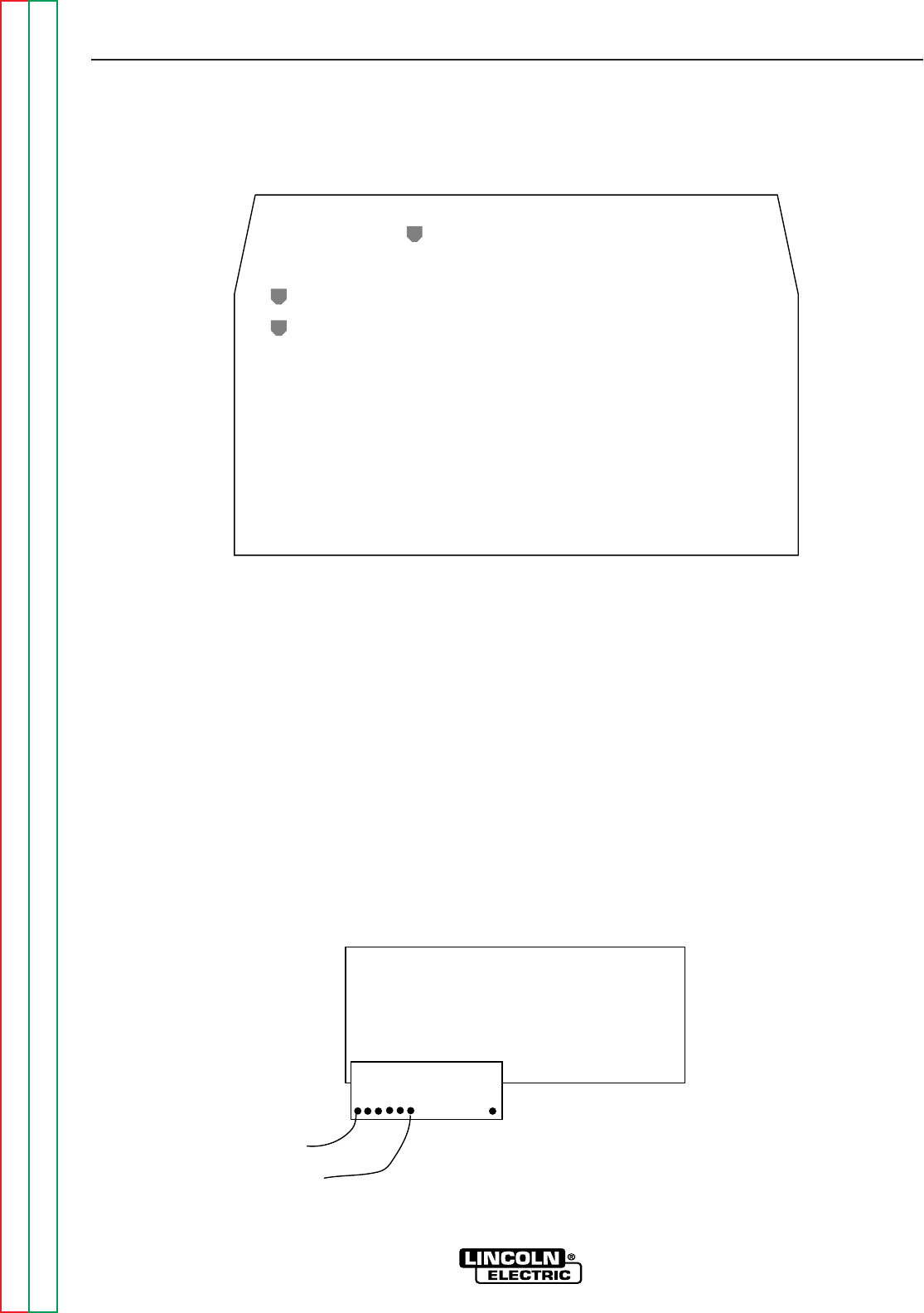
CONTROL BOARD LED DEFINITIONS
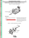
LED1: (Red) This light indicates that 18 VAC is
being supplied to the control board from the
auxiliary transformer. It also shows that the 18
VAC is being rectified and should be regulated to
+15 VDC. This +15 VDC supply is used to power
the circuitry on the control board.
LED2: (Red) This light indicates that the +5.5
VDC is present. This voltage is derived from the
+15 VDC supply. The +5.5 VDC supply is used
to power the circuitry on the control board.
LED3: (Red) This light indicates that 18 VAC is
being supplied to the control board from the
auxiliary transformer. It also shows that the 18
VAC is being rectified and should be regulated to
-15 VDC. This 15 VDC supply is used to power
the circuitry on the control board.
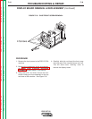
FIGURE F.14 – CONTROL BOARD LEDs
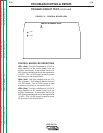
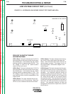
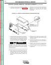
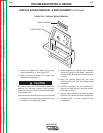
FIGURE F.15 – DISPLAY BOARD TEST POINTS
PRO-CUT 55 CONTROL G3328
LED2
LED1
LED3
L10721 DISPLAY BOARD
(REAR VIEW)
J 40
1
15
#219
#216
PRO-CUT 80 CONTROL G3443