


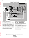
THEORY OF OPERATION
E-4 E-4
PRO-CUT 80
Return to Section TOC Return to Section TOC Return to Section TOC Return to Section TOC
Return to Master TOC Return to Master TOC Return to Master TOC Return to Master TOC
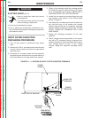
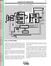
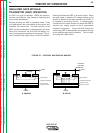
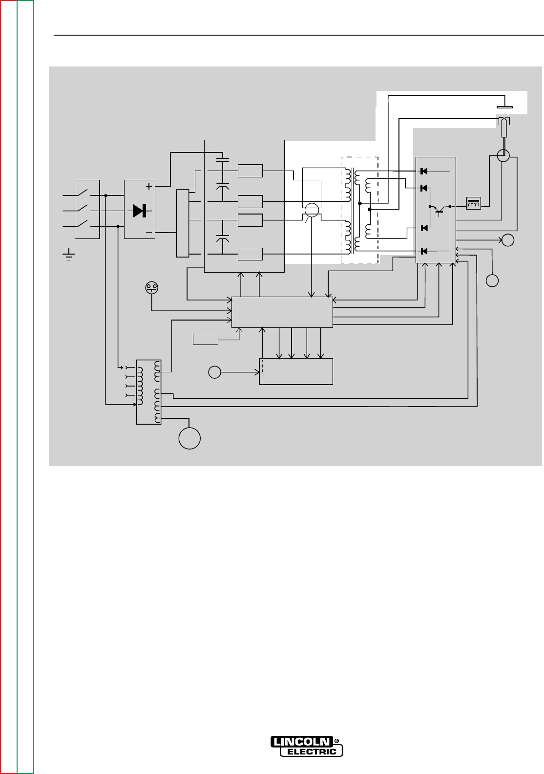
FIGURE E.4 – MAIN TRANSFORMER
INPUT
LINE
SWITCH
INPUT
RECTIFIER
FAN
MOTOR
"A"
L
E
A
D
AUXILIARY
TRANSFORMER
OUTPUT
CONTROL
AIR
PRESSURE
SWITCH
P
R
O
T
E
C
T
O
N
I
SIGNAL
CR 1
DRIVE
SIGNAL
RELAY
IGBT
GATE
SIGNALS
R
E
A
D
Y
A
I
R
L
O
W
T
H
E
R
M
A
L
S
A
F
E
Y
T
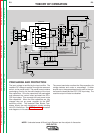
TRIGGER & SAFETY
ELECTRODE & TRANSFER
CURRENT FEEDBACK
PILOT ENABLE
ELECTRODE SOLENOID ENABLE
AIR SOLENOID ENABLE
AIR
SOLENOID
TRIGGER & SAFETY
E
L
E
C
T
R
O
D
E
S
O
L
E
N
O
I
D
TORCH
CONNECTOR
ELECTRODE
NOZZLE
WORK
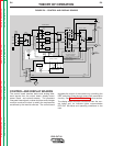
R
E
C
O
N
N
E
C
T
S
W
T
C
H
I
POWER BOARD
CR 1
RELAY
IGBT
IGBT
IGBT
IGBT
CAPACITOR
CAPACITOR
CURRENT
TRANSFORMER
CONTROL BOARD
DISPLAY BOARD
18/36VAC
12VAC
24VAC
MAIN
TRANSFORMER
OUTPUT BOARD
CHOKE
PILOT
TRANSISTOR
THERMOSTATS
115VAC
REMOTE
INTERFACE
RECEPTACLE
&
2
& 2
MAIN TRANSFORMER
Each IGBT pair acts as a switch assembly. Each
assembly feeds a separate, oppositely wound primary
winding of the main transformer. The reverse direction
of current flow through the main transformer primaries
and the offset timing of the IGBT pairs induce an AC
square wave output signal at the secondary of the
main transformer.
The DC current flow through each primary winding is
redirected or "clamped" back to each respective filter
capacitor when the IGBTs are turned off. This is need-
ed due to the inductance of the transformer primary
winding.
The primary currents also pass through the current
transformer, which sends a signal to the control board.
If the primary currents are not equal, the control board
compensates by adjusting the IGBT gate signals.
The firing of both IGBT pairs occurs during halves of
the 50 microsecond intervals, creating a constant
20KHZ output.
The secondary portion of the main transformer is made
up of two separate windings. One secondary winding
supplies the electrode-to-work voltage. This is the
high current winding, which is capable of supplying
maximum output current during the cutting process.
The other secondary winding supplies the electrode-
to-nozzle voltage for the pilot arc current. The con-
ductor in this winding is smaller since the pilot current
is considerably less than the cutting current. While
one winding is conducting the other winding is at a lim-
ited voltage and aids in the arc transfer to and from the
workpiece.