


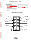
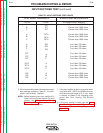
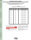
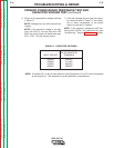

TEST POINT TERMINALS ANALOG METER X10 RANGE
+Probe - Probe Acceptable Meter Readings
Return to Section TOC Return to Section TOC Return to Section TOC Return to Section TOC
Return to Master TOC Return to Master TOC Return to Master TOC Return to Master TOC
TROUBLESHOOTING & REPAIR
F-14 F-14
PRO-CUT 80
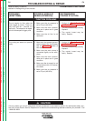
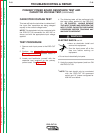
6. If the input rectifier does not meet the accept-
able readings outlined in Table F.1, the com-
ponent may be faulty. Replace.
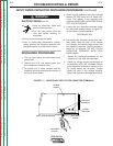
NOTE: Before replacing the input rectifier (D1)
check the input power switch (S1) and
perform the Primary Power Board
Resistance Test. Also check for leaky
or faulty filter capacitors.
7. If the input rectifier is good, be sure to recon-
nect leads #207, #207A and #209 to the cor-
rect terminals and torque to 31 in.-lbs. Apply
a coating of Essex D-4-8 insulating com-
pound and Dow Corning 738 Silicone
Sealant.
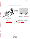
8. If the input rectifier is faulty, see the Input
Rectifier Bridge Removal & Replacement
procedure. See the Wiring Diagram and
Figure F.2.
INPUT RECTIFIER TEST (continued)
TABLE F.1 INPUT RECTIFIER TEST POINTS
A
B
C
A
B
C
A
B
C
207
207
207
207A
207A
207A
209
209
209
207
207
207
207A
207A
207A
209
209
209
A
B
C
A
B
C
A
B
C
Greater than 1000 ohms
Greater than 1000 ohms
Greater than 1000 ohms
Greater than 1000 ohms
Greater than 1000 ohms
Greater than 1000 ohms
Less than 100 ohms
Less than 100 ohms
Less than 100 ohms
Less than 100 ohms
Less than 100 ohms
Less than 100 ohms
Less than 100 ohms
Less than 100 ohms
Less than 100 ohms
Greater than 1000 ohms
Greater than 1000 ohms
Greater than 1000 ohms