


Be sure to follow the safety practice to
use the female connector on the cable
which would normally be electrically "hot"
(supply lead) if disconnected when the
system is energized, and the male on the
normally “cold” (load lead) side. If practical, shut off
power before connecting or disconnecting terminals.
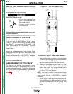
WORK CONNECTION
Each Converter in the Multi-Weld system must have its
individual “Work” lead connected (clipped) to the work.
The #3 AWG (27 mm
2
) Work clip lead must have clean
metal connection to the work to complete the DC input
supply and output power circuits of the Multi-Weld 350.
Do not disconnect the Work clip lead without first
switching OFF the Converter panel switch. Failure to
do so will allow the Work lead clip to be electrically “hot”
to work and “hot” to the electrode, through the circuit of
the Converter, for about 5 seconds until the input con-
tactor opens.
CASE GROUNDING
As shipped, the case of the Multi-Weld 350 is isolated
from all of the DC input and output welding terminals.
It is equipped with a grounding terminal screw
(.31” / 7.9 mm) marked with the symbol located on
the bottom rear of the base assembly. (Refer to the bot-
tom view figure.) In order to comply with CSA and UL
case grounding specifications, this terminal is provided
for connection to weldment work that must be properly
grounded per methods meeting local and national elec-
trical codes. Refer to “Safety in Welding, Cutting and
Allied Processes,” ANSI Z49.1 (US) and W117.2
(Canada).
Since any case fault would only involve the DC welding
circuit, the size of the grounding lead should have the
capacity to ground the potential fault current without
burning open. Use at least #6 AWG (13 mm
2
), but need
not exceed the size of the input cable supplying the
Multi-Weld 350.
Connect the Multi-Weld grounding lead to the work
piece separately from the Work clip. If the same clip is
used for both ground and work connection, the Multi-
Weld case will be electrically “hot” to the work if the clip
is removed without first switching OFF the panel
switch. ( Refer to the Work clip WARNING).
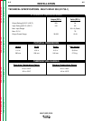
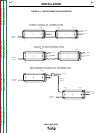
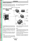
INTER-CONNECTION OF
CONVERTERS
The input and electrode cables of the Multi-Weld 350
Converters may be inter-connected in a Multi-Weld
system using any combination of Distribution Box(es)
(see Figure B.1), paralleling (CC mode only) and
“daisy-chaining” (see Figure A.2). Choose the config-
uration that best fits the field application setup within
the capacity of the power source supplying the system.
Power Source (Volts x Amp) capacity > 1.1 x
Sum of Converters’ (Volts x Amps) arcs
Paralelled units may be powered from more than one
source. Disconnect all inputs, including outputs from
other sources, before working on the equipment.
Before removing the parallel jumper, be sure both
Converters are switched OFF. If not, the male side of
the first disconnection will be electrically “hot” to work.
A-4 A-4
INSTALLATION
MULTI-WELD 350
Return to Section TOC Return to Section TOC Return to Section TOC Return to Section TOC
Return to Master TOC Return to Master TOC Return to Master TOC Return to Master TOC
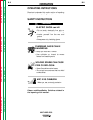
WARNING
WARNING
WARNING