


TROUBLESHOOTING & REPAIR
F-16 F-16
MULTI-WELD 350
Return to Section TOC Return to Section TOC Return to Section TOC Return to Section TOC
Return to Master TOC Return to Master TOC Return to Master TOC Return to Master TOC
MULTI-WELD 350
LINCOLN
ELECTRIC
AMPS
VOL
TS
A
V
ELECTRODE
INPUT
WORK
CHOPPER TECHNOLOGY
POWER
MODULE
CAPACITOR
TERMINALS
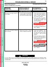
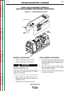
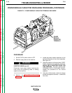
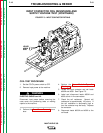
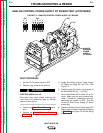
FIGURE F.2 – POWER MODULE CAPACITOR TERMINAL DISCHARGE
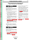
POWER MODULE CAPACITOR DISCHARGE PROCEDURE (CONTINUED)
PROCEDURE
1. Set the CC/CV power switch to OFF.
2. Remove input power to the machine.
ELECTRIC SHOCK can kill.
Disconnect input power before removing the
case cover and performing tests or making
repairs to the machine.
3. Perform the Case Cover Assembly
Removal procedure.
4. Locate the power module capacitors on the
right and left sides of the tunnel assembly.
See Figure F.2.
5. Using the resistor and jumper leads, CARE-
FULLY discharge the capacitor terminals.
NEVER USE A SHORTING STRAP FOR
THIS PURPOSE. DO NOT TOUCH THE
TERMINALS WITH YOUR BARE HANDS.
Repeat the procedure for the second
capacitor.
6. Using the volt/ohmmeter, check the voltage
across the capacitor terminals. It should be
zero volts.
WARNING