


TROUBLESHOOTING & REPAIR
F-37 F-37
MULTI-WELD 350
Return to Section TOC Return to Section TOC Return to Section TOC Return to Section TOC
Return to Master TOC Return to Master TOC Return to Master TOC Return to Master TOC
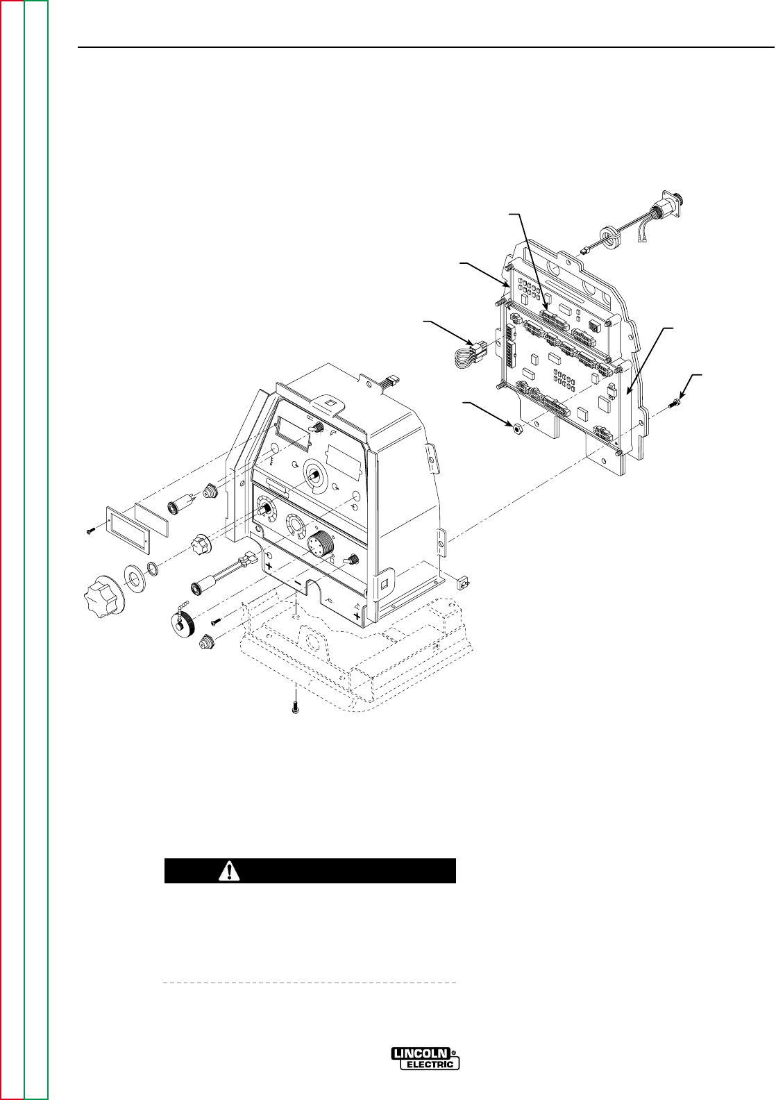
PERIPHERAL
PC BOARD
JUMPER
PLUG P3
PLUG P31
SCREWS
(7)
WELD
CONTROL
PC BOARD
NUTS
HOT START ARC FORCE
OTE
CC
SLOPE
PIPE
STICK 7018
GOUGE
L11141-2
CC
CV
OFF
AMPS
VOLTS
A
V
MULTI-WELD 350
LINCOLN
ELECTRIC
ELECTRODE
INPUT
WORK
CHOPPER TECHNOLOGY
4 4
2
2
0
6 6
10
10
8
8
5
4
3
2
0
6
10
9
8
7
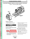
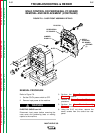
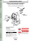
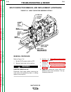
FIGURE F.8 – CASE FRONT ASSEMBLY DETAILS
WELD CONTROL OR PERIPHERAL PC BOARD
REMOVAL AND REPLACEMENT (CONTINUED)
REMOVAL PROCEDURE
Refer to Figure F.8.
1. Set the CC/CV power switch to OFF.
2. Remove input power to the machine.
ELECTRIC SHOCK can kill.
Disconnect input power before removing the
case cover and performing tests or making
repairs to the machine.
3. Perform the Case Cover Assembly
Removal procedure.
4. Perform the Power Capacitor Discharge
procedure.
5. Perform the Case Front Assembly
Removal procedure.
6. Using the 5/16" nut driver, remove the
seven screws from the control box rear
panel.
WARNING