


TROUBLESHOOTING & REPAIR
F-24 F-24
MULTI-WELD 350
Return to Section TOC Return to Section TOC Return to Section TOC Return to Section TOC
Return to Master TOC Return to Master TOC Return to Master TOC Return to Master TOC
MULTI-WELD 350
LINCOLN
ELECTRIC
AMPS
VOL
TS
A
V
ELECTRODE
INPUT
WORK
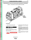
CHOPPER TECHNOLOGY
DC BUSS
POWER
SUPPLY
PC BOARD
P46
P47
1 2 1 2 3 4
5 6 7 8 3 4
P46
P47
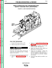
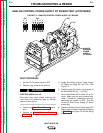
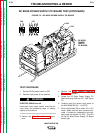
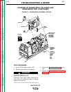
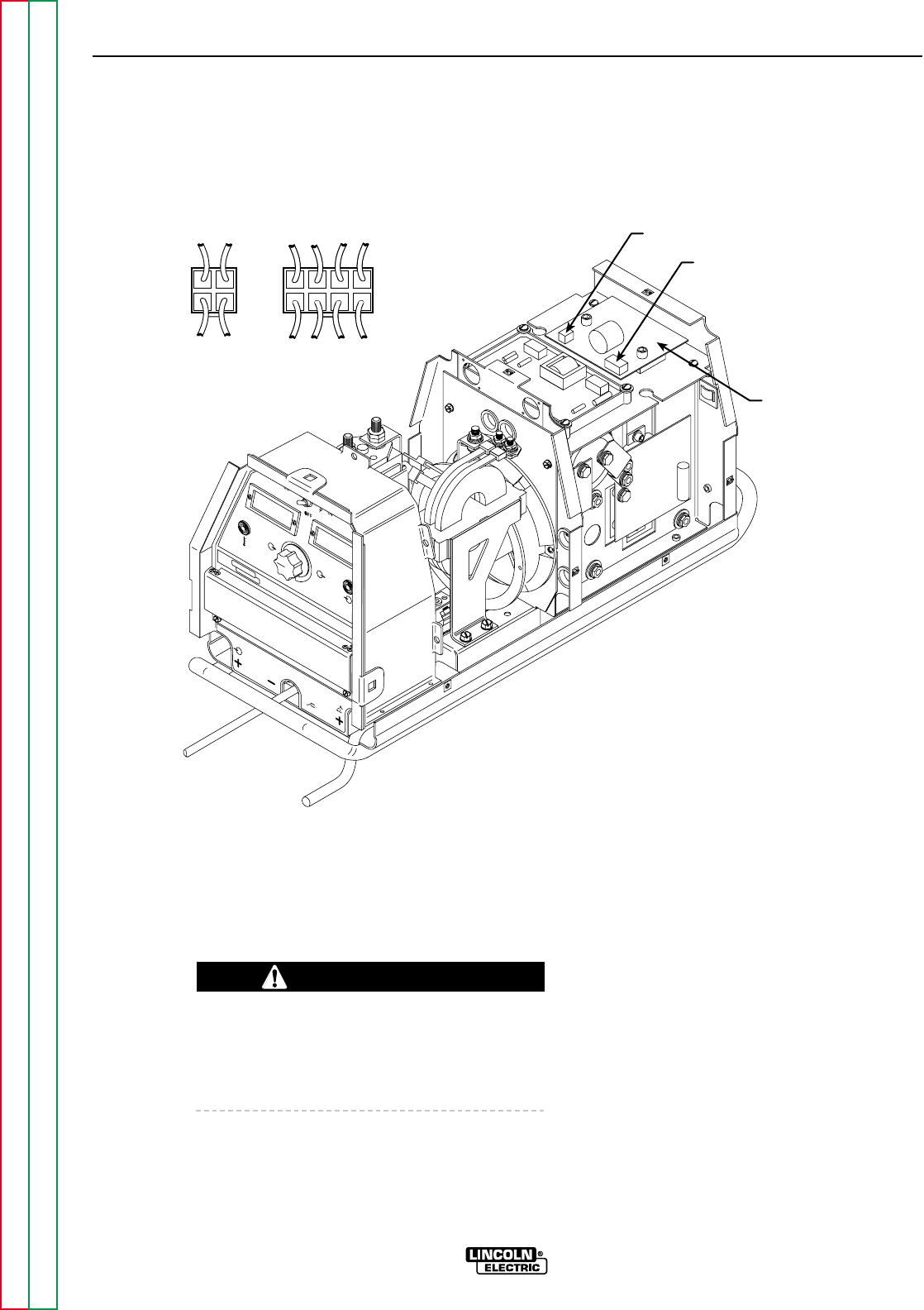
FIGURE F.5 – DC BUSS POWER SUPPLY PC BOARD
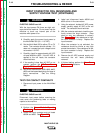
DC BUSS POWER SUPPLY PC BOARD TEST(CONTINUED)
TEST PROCEDURE
1. Set the CC/CV power switch to OFF.
2. Remove input power to the machine.
ELECTRIC SHOCK can kill.
Disconnect input power before removing the
case cover and performing tests or making
repairs to the machine.
3. Perform the Case Cover Removal proce-
dure.
4. Perform the Power Module Capacitor
Discharge procedure.
5. Locate the DC Buss Power Supply PC
Board and plugs P46 and P47. See Figure
F.5.
6. Carefully apply the correct input power to
the Multi-Weld 350 (50 – 113 VDC).
7. Set the Multi-Weld 350 to either CC or CV
mode. Make sure the input contactor acti-
vates. If it does not, increase the input volt-
age but do not exceed 113 VDC. The LED
on the DC Buss Power Supply PC Board
should light.
WARNING