


Troubleshooting & Repair Section......................................................................................Section F
How to Use Troubleshooting Guide ...........................................................................................F-2
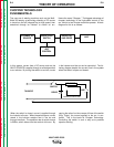
PC Board Troubleshooting Procedures ......................................................................................F-3
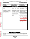
Troubleshooting Guide ....................................................................................................F-4 - F-12
Test Procedures .......................................................................................................................F-13
Case Cover Assembly Removal and Replacement Procedure .........................................F-13
Power Module Capacitor Discharge Procedure ................................................................F-15
Input Contactor Coil Resistance and Supply Voltage Test .................................................F-17
Analog Control Power Supply PC Board Test ....................................................................F-20
DC Buss Power Supply PC Board Test..............................................................................F-23
Chopper PC Board Input Voltages and Resistance Tests..................................................F-26
Oscilloscope Waveforms ..........................................................................................................F-29
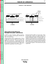
Normal Open Circuit Voltage Waveform (CC Mode) –
Input Voltage Applied 75 VDC ...........................................................................................F-29
Normal Open Circuit Voltage Waveform (CV Mode) –
Output Control at Maximum................................................................................................F-30
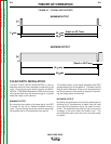
Normal Weld Voltage Waveform (CC Stick Mode) –
Machine Loaded to 350 Amps at 34 Volts..........................................................................F-31
Normal Weld Voltage Waveform (CV Mode) –
Machine Loaded to 350 Amps at 34 Volts..........................................................................F-32
Normal Open Circuit Voltage Waveform (CV Mode) –
Output Control at Maximum................................................................................................F-33
Replacement Procedures .........................................................................................................F-34
Case Front Assembly Removal and Replacement.............................................................F-34
Weld Control Board Removal and Replacement ...............................................................F-36
Amps/Volts Digital Meter and Potentiometer Removal and Replacement .........................F-39
Input Contactor Removal and Replacement.......................................................................F-42
Input Diode Removal and Replacement.............................................................................F-45
Fan Motor Assembly Removal and Replacement ..............................................................F-48
Power Capacitor Removal and Replacement.....................................................................F-51
Chopper PC Board and Diode Module Removal and Replacement .................................F-54
Diode Module Removal and Replacement.........................................................................F-57
Retest After Repair ...................................................................................................................F-60
Section F-1 Section F-1
TABLE OF CONTENTS
- TROUBLESHOOTING & REPAIR SECTION -
MULTI-WELD 350
Return to Master TOC Return to Master TOC Return to Master TOC Return to Master TOC