


TROUBLESHOOTING & REPAIR
F-18 F-18
MULTI-WELD 350
Return to Section TOC Return to Section TOC Return to Section TOC Return to Section TOC
Return to Master TOC Return to Master TOC Return to Master TOC Return to Master TOC
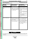
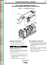
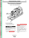
LEADS
#303A
#330
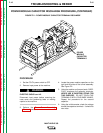
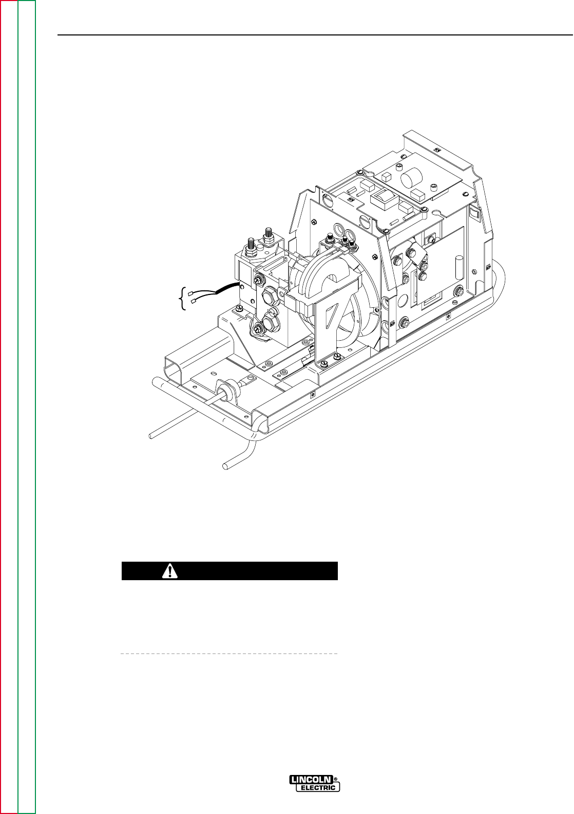
FIGURE F.3 – INPUT CONTACTOR DETAILS
INPUT CONTACTOR COIL RESISTANCE AND
SUPPLY VOLTAGE TEST (CONTINUED)
COIL TEST PROCEDURE
1. Set the CC/CV power switch to OFF.
2. Remove input power to the machine.
ELECTRIC SHOCK can kill.
Disconnect input power before removing the
case cover and performing tests or making
repairs to the machine.
3. Perform the Case Cover Removal proce-
dure.
4. Perform the Power Module Capacitor
Discharge procedure.
5. Locate the input contactor and coil leads
#303A and #330. See Figure F.3.
6. Label and disconnect leads #303A and
#330 at their in-line connectors.
7. Check the coil resistance. Normal coil
resistance is approximately 100 ohms. If
the coil resistance is abnormally high or
low, the contactor may be faulty. Replace
the contactor.
8. Reconnect leads #303A and #330 to the
coil leads.
WARNING