


TROUBLESHOOTING & REPAIR
F-38 F-38
MULTI-WELD 350
Return to Section TOC Return to Section TOC Return to Section TOC Return to Section TOC
Return to Master TOC Return to Master TOC Return to Master TOC Return to Master TOC
WELD CONTROL OR PERIPHERAL PC BOARD
REMOVAL AND REPLACEMENT (CONTINUED)
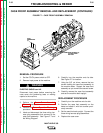
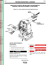
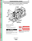
7. Carefully label and remove the 12 molex
plugs from the Weld Control PC board.
Press and hold the keeper on each plug as
you remove it. Also remove plug P31 from
the Peripheral PC Board as shown in
Figure F.8. This will allow the assembly to
lie flat.
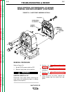
8. Using the 3/8" nut driver, remove the four
nuts holding the Weld Control PC Board in
place.
NOTE: Verify the orientation of the Weld Con-
trol PC Board for replacement. You may need
to remove a nut on the Peripheral PC Board in
order to free the Weld Control PC Board.
9. Carefully remove the Weld Control PC
Board.
NOTE: It may be necessary to pry gently on the
PC Board to remove it.
REPLACEMENT PROCEDURE
1. Set the Weld Control PC Board squarely
onto the studs and press it in place. Verify
proper orientation. Replace any nuts
removed from the Peripheral PC Board at
disassembly.
2. Tighten the four 3/8" nuts holding the board
in place.
3. Attach the molex plugs, including the plug
removed from the Peripheral PC Board at
disassembly. See the Wiring Diagram.
NOTE: Make sure jumper plug P3 is in place.
4. Attach the rear panel with seven 5/16"
screws.
5. Perform the Case Front Assembly
Replacement procedure.
6. Perform the Case Cover Assembly
Replacement procedure.