


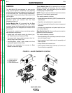
GENERAL DESCRIPTION
The MULTI-WELD 350 Converter uses a single DC
input power source to provide up to 350 continuous
amps for positive polarity stick, wire processes, and
arc-air gouging. The machine converts higher volt-
age/lower current DC input power to lower
voltage/higher current DC output power with over 90%
efficiency. This DC output is controlled by Chopper
Technology to produce DC current for multi-purpose
welding applications.
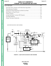
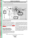
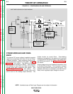
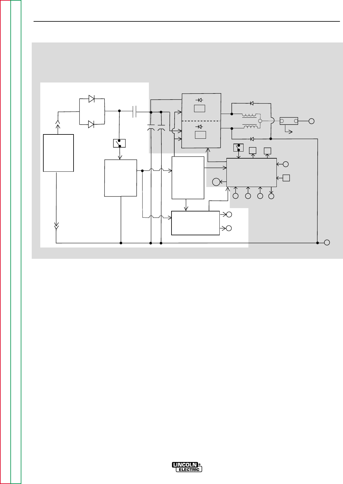
INPUT POWER SOURCE,
CONTACTOR AND DC BUSS
POWER SUPPLY BOARD
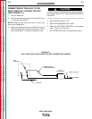
The Multi-Weld 350 receives DC input power from an
80 VDC buss Multi-Source (recommended), although
other external DC sources such as the Lincoln Electric
DC-1000, DC-655, or DC-600 can be used if they pro-
duce 50 VDC or above.
The +50 VDC supply voltage is applied to the input
contactor via two large input diodes. The input contac-
tor establishes the electrical connection between the
Multi-Weld 350 and the power source when the
ON/OFF MODE switch is activated in either the con-
stant current (CC-stick) mode or the constant voltage
(CV-wire) mode.
A 40 VDC Buss Power Supply Board supplies 40 VDC
power to the Analog Control Power Supply Board,
which in turn feeds regulated voltages to a Weld
Control Board and 15 VDC to the Peripheral Board.
The Peripheral Board powers the input contactor coil
and the input indicator light on the front panel. The 40
VDC is also supplied to the Peripheral Board and is
passed on to the Weld Control Board.
E-2 E-2
THEORY OF OPERATION
MULTI-WELD 350
Return to Section TOC Return to Section TOC Return to Section TOC Return to Section TOC
Return to Master TOC Return to Master TOC Return to Master TOC Return to Master TOC
CHOKE
IGBT
IGBT
SHUNT
WORK
TO ELECTRODE
CABLE
+
ANALOG
CONTROL
POWER
SUPPLY
BOARD
WELD
CONTROL
BOARD
ARC
FORCE
CONTROL
OUTPUT
CONTROL
HOT
START
DC
BUS
POWER
SUPPLY
BOARD
FAN
+
DC
POWER
SOURCE
(EXTERNAL)
_
REMOTE
RECEPTACLE
INPUT
DIODES
INPUT
CONTACTOR
MULTI-WELD 350 BLOCK LOGIC DIAGRAM
CC SLOPE
(STICK/GOUGE or PIPE)
PERIPHERAL
BOARD
INPUT
INDICATOR
LIGHT
ON/OFF
MODE
SWITCH
(1/2)
CR1
CHOPPER MODULE
CHOPPER MODULE
ON/OFF
MODE
SWITCH
(1/2)
VOLTS
AMPS
THERMAL
LIGHT
FREEWHEELING DIODE
FREEWHEELING DIODE
REGULATED
VOLTAGES
CR1
COIL
15 VDC
CURRENT FEEDBACK
TO WELD CONTROL BOARD
20
VDC
x 2
-
INPUT
CAPACITORS
40
VDC
LEFT AND RIGHT
CHOPPER MODULES
GATE
SIGNALS
40 VDC
FIGURE E.2 – INPUT POWER SOURCE, CONTACTOR AND DC BUSS POWER SUPPLY BOARD
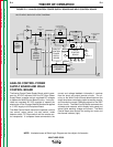
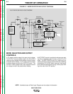
NOTE: Unshaded areas of Block Logic Diagram are the subject of discussion.