


TROUBLESHOOTING & REPAIR
F-41 F-41
MULTI-WELD 350
Return to Section TOC Return to Section TOC Return to Section TOC Return to Section TOC
Return to Master TOC Return to Master TOC Return to Master TOC Return to Master TOC
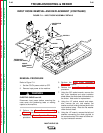
AMPS/VOLTS DIGITAL METER AND POTENTIOMETER
REMOVAL AND REPLACEMENT (CONTINUED)
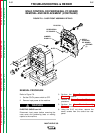
7. Carefully remove the Amps or Volts Digital
Meter molex plug from the Weld Control
PC Board. Press and hold the keeper on
the plug as you remove it.
8. Using the 5/16" nut driver, remove the two
nuts and flat washers holding the Amps or
Volts Digital Meter in place.
9. Using the phillips screw driver, remove the
two screws holding the bezel and lens (and
the meter) to the front panel.
10. Carefully remove the Amps or Volts Digital
Meter. Do not damage the gasket.
REPLACEMENT PROCEDURE
1. Fit the meter into position, adjustable slot
side down. Verify that the gasket is in place.
2. Insert the two phillips screws through the
bezel, and with the lens in place, tighten
the screws into the meter.
3. Install the flat washers and 5/16" nuts onto
the screws and tighten them.
4. Attach the molex plug to the Weld Control
PC Board. See the Wiring Diagram.
5. Attach the rear panel with seven 5/16"
screws.
6. Perform the Case Front Assembly
Replacement procedure.
7. Perform the Case Cover Assembly
Replacement procedure.
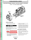
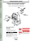
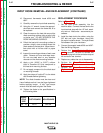
OUTPUT CONTROL POTENTIOMETER
REMOVAL PROCEDURE
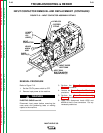
Refer to Figure F.9.
1. Set the CC/CV power switch to OFF.
2. Remove input power to the machine.
ELECTRIC SHOCK can kill.
Disconnect input power before removing the
case cover and performing tests or making
repairs to the machine.
3. Perform the Case Cover Assembly
Removal procedure.
4. Perform the Power Capacitor Discharge
procedure.
5. Perform the Case Front Assembly
Removal procedure.
6. Using the 5/16" nut driver, remove the
seven screws from the control box rear
panel.
7. Carefully remove the potentiometer molex
plug from the Weld Control PC Board.
Press and hold the keeper on the plug as
you remove it.
8. Using the diagonal cutters, cut the cable tie
holding the potentiometer to the back
panel.
9. Using the allen wrench, remove the set
screw holding the potentiometer knob to
the shaft.
10. Remove the knob, shaft seal, and spacer.
Pull the potentiometer out from the panel.
REPLACEMENT PROCEDURE
1. Fit the potentiometer into position, verifying
proper orientation. Install a new cable tie.
2. Install the spacer, shaft seal, and knob.
3. Tighten the knob onto the shaft with the set
screw.
4. Attach the molex plug to the Weld Control
PC Board. See the Wiring Diagram.
5. Attach the rear panel with seven 5/16"
screws.
6. Perform the Case Front Assembly
Replacement procedure.
7. Perform the Case Cover Assembly
Replacement procedure.
WARNING