


TROUBLESHOOTING & REPAIR
F-19 F-19
MULTI-WELD 350
Return to Section TOC Return to Section TOC Return to Section TOC Return to Section TOC
Return to Master TOC Return to Master TOC Return to Master TOC Return to Master TOC
INPUT CONTACTOR COIL RESISTANCE AND
SUPPLY VOLTAGE TEST (CONTINUED)
ELECTRIC SHOCK can kill.
With the input power ON, there are high volt-
ages inside the machine. Do not reach into the
machine or touch any internal part of the
machine while power is on.
9. Carefully apply the correct input power to
the Multi-Weld 350 (50 – 113 VDC).
10. Set the Multi-Weld 350 to either CC or CV
mode. The contactor should activate. If it
does not, increase the input voltage but do
not exceed 113 VDC.
11. Carefully check for approximately 40 VDC
at leads #303A to #330. If the 40 VDC is
applied to the coil leads, the contactor
should activate.
12. If the reading is less than 40 VDC or not
present, perform the DC Buss Power
Supply PC Board Test.
13. Also check leads #303A, #330, #303, #403,
#230 and their associated plugs for loose or
faulty connections. See the Wiring
Diagram.
TEST FOR CONTACT CONTINUITY
1. Disconnect input power to the Multi-Weld
350.
ELECTRIC SHOCK can kill.
Disconnect input power before removing the
case cover and performing tests or making
repairs to the machine.
2. Perform the Power Module Capacitor
Discharge procedure.
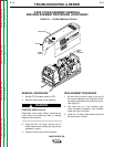
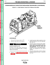
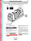
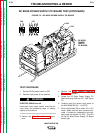
3. Locate the input contactor and coil leads
#303A and #330. See Figure F.3.
4. Label and disconnect leads #303A and
#330 at their in-line connectors.
5. Using the external, isolated 40 VDC power
supply, carefully apply 40 VDC to the coil
leads. The contactor should activate.
6. With the contactor activated, check the con-
tinuity across the large contacts. (Zero
ohms or very low resistance is normal.)
See Figure F.3. If the resistance is high,
the input contactor is faulty. Replace the
input contactor.
7. When the contactor is not activated, the
resistance should be infinite or very high
across the contacts. If the resistance is low,
the input contactor is faulty. Replace the
input contactor.
8. Remove the 40 VDC external supply and
reconnect the coil leads previously
removed.
9. If finished testing, perform the Case Cover
Replacement procedure.
WARNING
WARNING