


TROUBLESHOOTING & REPAIR
F-43 F-43
MULTI-WELD 350
Return to Section TOC Return to Section TOC Return to Section TOC Return to Section TOC
Return to Master TOC Return to Master TOC Return to Master TOC Return to Master TOC
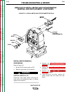
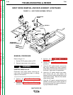
LEADS
#303A
#330
LEADS
#X1A
#X1
#XBP5
INPUT
CONTACTOR
LEAD #331
COPPER
STRAP
HEAT SINK
BOLTS & NYLON
INSULATORS (2)
BASE
BOLTS (2)
INPUT DIODE
HEAT SINK
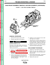
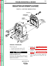
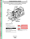
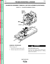
FIGURE F.10 – INPUT CONTACTOR ASSEMBLY DETAILS
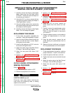
INPUT CONTACTOR REMOVAL AND REPLACEMENT (CONTINUED)
REMOVAL PROCEDURE
Refer to Figure F.10.
1. Set the CC/CV power switch to OFF.
2. Remove input power to the machine.
ELECTRIC SHOCK can kill.
Disconnect input power before removing the
case cover and performing tests or making
repairs to the machine.
3. Perform the Case Cover Assembly
Removal procedure.
4. Perform the Power Capacitor Discharge
procedure.
5. Perform the Case Front Assembly
Removal procedure.
6. Label and disconnect leads #330 and
#303A at their in-line connectors. Cut any
necessary cable ties.
WARNING