


TROUBLESHOOTING & REPAIR
F-35 F-35
MULTI-WELD 350
Return to Section TOC Return to Section TOC Return to Section TOC Return to Section TOC
Return to Master TOC Return to Master TOC Return to Master TOC Return to Master TOC
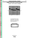
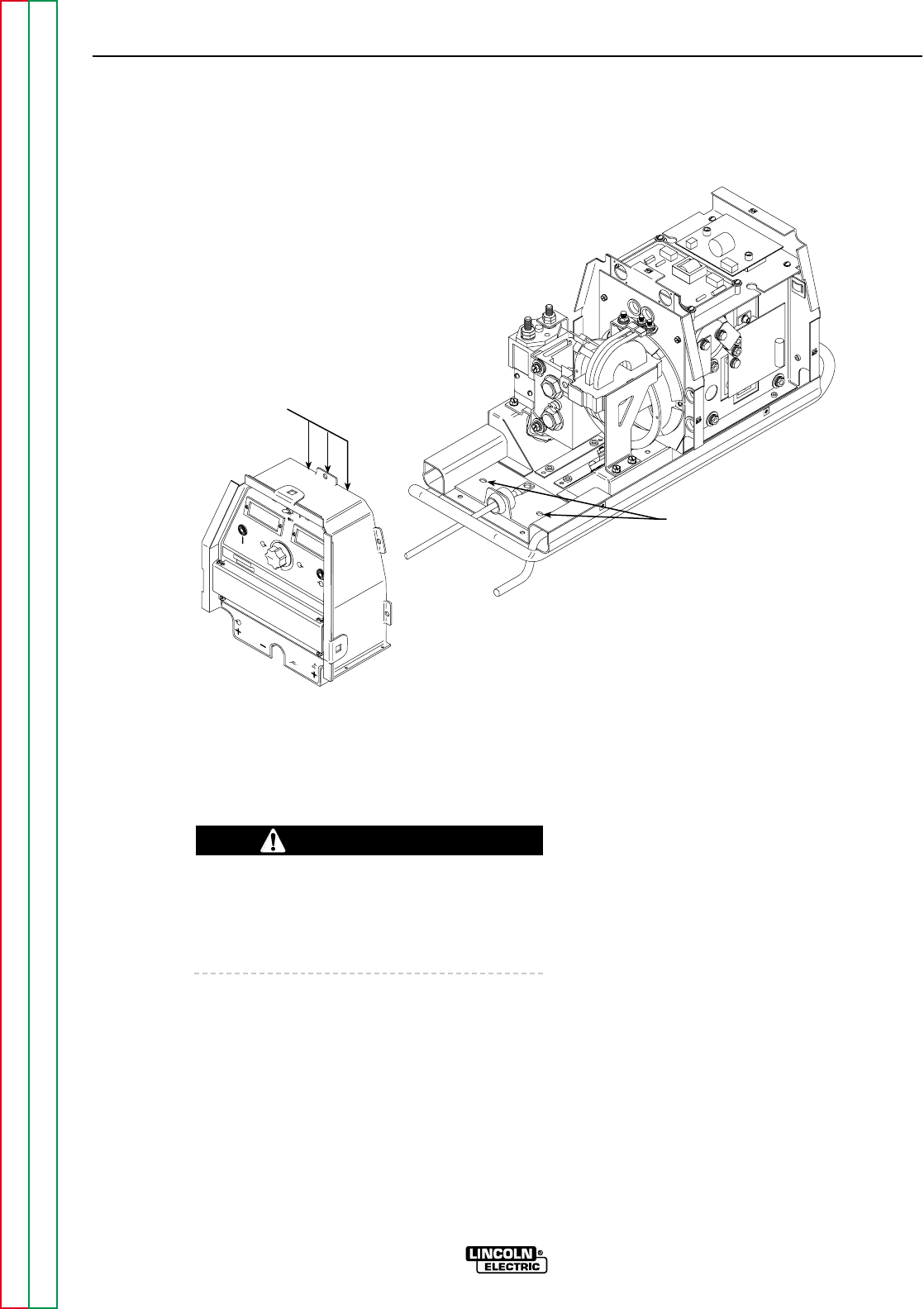
BASE SCREWS (2)
ACCESS FROM
BOTTOM
PLUG
ASSEMBLIES
(3)
MULTI-WELD 350
LINCOLN
ELECTRIC
AMPS
VOLTS
A
V
ELECTRODE
INPUT
WORK
CHOPPER TECHNOLOGY
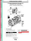
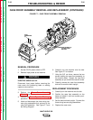
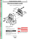
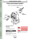
FIGURE F.7 – CASE FRONT ASSEMBLY REMOVAL
CASE FRONT ASSEMBLY REMOVAL AND REPLACEMENT (CONTINUED)
REMOVAL PROCEDURE
1. Set the CC/CV power switch to OFF.
2. Remove input power to the machine.
ELECTRIC SHOCK can kill.
Disconnect input power before removing the
case cover and performing tests or making
repairs to the machine.
3. Perform the Case Cover Assembly
Removal procedure.
4. Perform the Power Capacitor Discharge
procedure.
5. Label and disconnect the three wiring har-
ness plug assemblies that connect to the
case front assembly. See Figure F.7 and
the Wiring Diagram.
6. Carefully turn the machine onto its side.
See Figure F.7 for location.
7. Using the 3/8" nut driver, remove the two
screws holding the case front assembly to
the machine base. Support the case front
assembly as you remove the second screw.
8. Carefully remove the case front assembly
and set the machine back upright.
REPLACEMENT PROCEDURE
1. Carefully turn the machine onto its side.
2. Position the case front assembly on the
base and attach it with two screws previ-
ously removed.
3. Set the machine back upright. Connect the
three wiring harness plug assemblies.
4. Replace the case cover.
WARNING