


TROUBLESHOOTING & REPAIR
F-14 F-14
MULTI-WELD 350
Return to Section TOC Return to Section TOC Return to Section TOC Return to Section TOC
Return to Master TOC Return to Master TOC Return to Master TOC Return to Master TOC
MUL
MUL
TI-WELD 350
TI-WELD 350
MULTI-WELD 350
LINCOLN
ELECTRIC
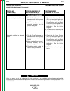
A
M
P
S
V
O
L
T
S
A
V
ELECTROD E
INPUT
WORK
CHOPPER TE CHNOLOGY
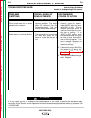
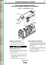
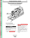
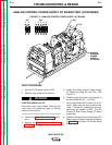
CASE COVER
FRONT
SCREW
HOLE (13)
TOROID
RING
LOCATION
FIGURE F.1 – COVER REMOVAL DETAILS
CASE COVER ASSEMBLY REMOVAL
AND REPLACEMENT PROCEDURE (CONTINUED)
REMOVAL PROCEDURE
1. Set the CC/CV power switch to OFF.
2. Remove input power to the machine.
ELECTRIC SHOCK can kill.
Disconnect input power before removing the
case cover and performing tests or making
repairs to the machine.
3. Using the 3/8" nut driver, remove the 13
sheet metal screws holding the case cover
assembly in place.
4. Carefully lift the cover off the machine.
REPLACEMENT PROCEDURE
1. Be sure that the toroid rings on the top of
the tunnel assembly are lying flat and will
not restrict placement of the machine cover.
See Figure F.1.
2. The cover fits on in one direction only.
Verify front/back orientation, then carefully
lower the cover into place.
3. Install the 13 sheet metal screws that hold
the case cover in place.
WARNING