


TROUBLESHOOTING & REPAIR
F-46 F-46
MULTI-WELD 350
Return to Section TOC Return to Section TOC Return to Section TOC Return to Section TOC
Return to Master TOC Return to Master TOC Return to Master TOC Return to Master TOC
{
}
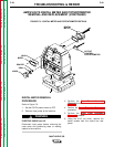
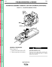
INPUT
TERMINAL
STRAP
BOLT
THERMOSTAT
(LEADS #306 ij)
MYLAR
CHOKE
ATTACHMENT
POINT
DIODE
PIGTAILS
MYLAR
HEAT
SINK
CONTACTOR
STRAP
CHOKE
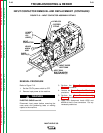
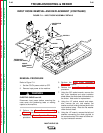
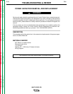
FIGURE F.11 – INPUT DIODE ASSEMBLY DETAILS
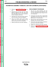
INPUT DIODE REMOVAL AND REPLACEMENT (CONTINUED)
REMOVAL PROCEDURE
Refer to Figure F.11.
1. Set the CC/CV power switch to OFF.
2. Remove input power to the machine.
ELECTRIC SHOCK can kill.
Disconnect input power before removing the
case cover and performing tests or making
repairs to the machine.
3. Perform the Case Cover Assembly
Removal procedure.
4. Perform the Power Capacitor Discharge
procedure.
5. Perform the Case Front Assembly
Removal procedure.
6. Perform the Input Contactor Removal
procedure.
7. Using the 3/8" socket wrench, remove the
bolt, nylon insulators and mylar insulation
sheet where the diode heat sink attaches to
the choke. Note order for replacement.
8. Using the 1/2" socket wrench and exten-
sion, remove the nut, lock washer, flat
washer, and bolt holding the heat sink to the
input terminal strap. Note the flat washer
under the bolt head.
9. Using the 1/2" wrench, remove the bolt and
washers connecting the diode pig-tails to
the contactor strap if this was not done dur-
ing input contactor removal.
WARNING