


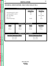
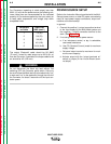
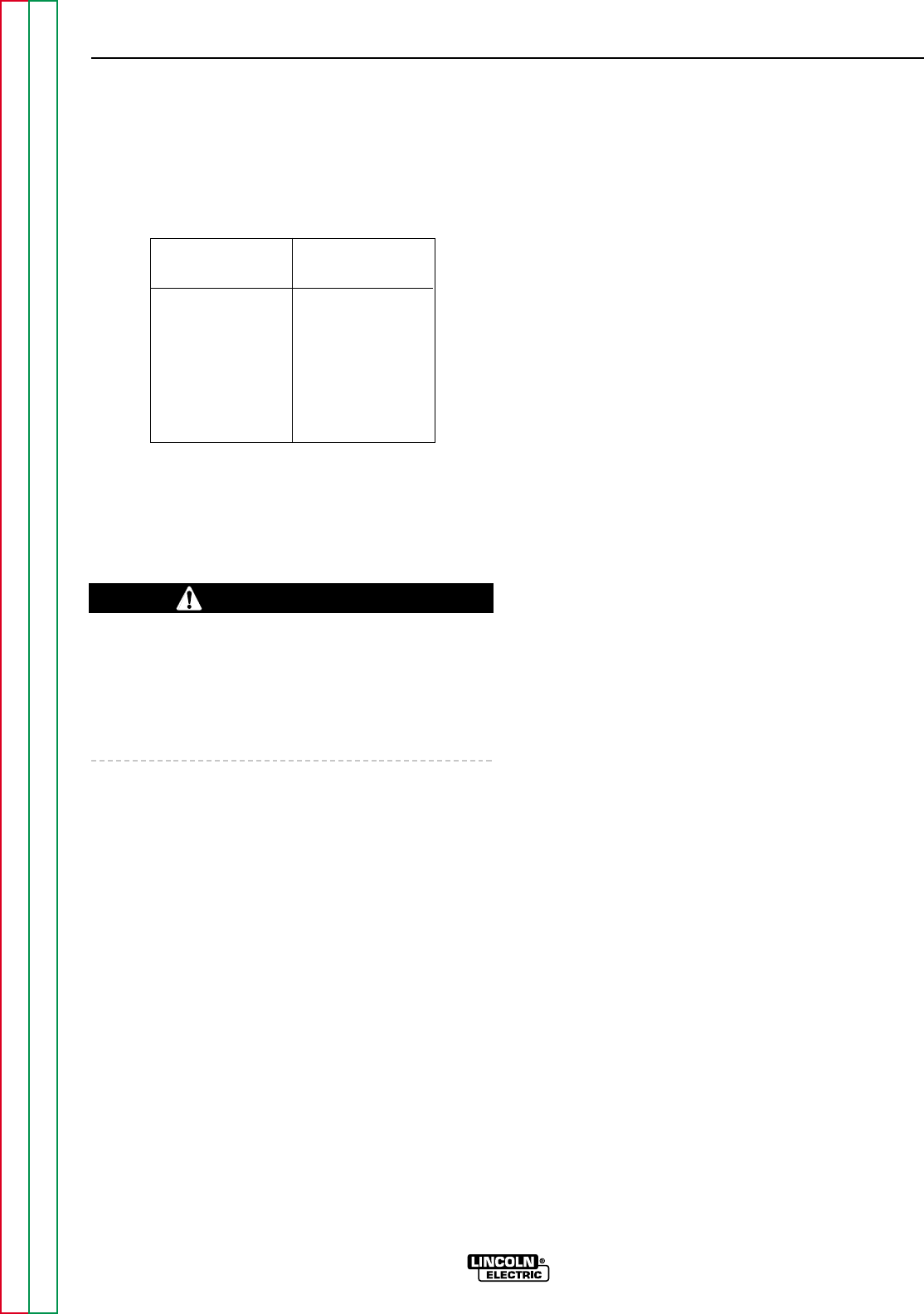
For Converters (operating at rated output) less than
200 ft. (61 m) from the power source, the following min-
imum cable sizes are recommended for the indicated
quantity of Converters supplied by the input cable run
to keep cable temperature and voltage drop within
acceptable limits:
Converters Cable Size
on Cable AWG (mm2 )
1 1/0 (50)
2 2/0 (70)
3 3/0 (95)
4 4/0 (120)
5 2x3/0 (2x95)
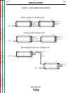
The output “Electrode” cable should be 2/0 AWG
(70 mm
2
) if sized for rated output up to 200 ft.(61 m)
from the Converter. If paralleled, the output cable to the
arc should be 4/0 (120 mm
2
).
Do not disconnect the Work clip lead without first
switching OFF the Converter panel switch. Failure to
do so will allow the Work lead clip to be electrically “hot”
to work and “hot” to the electrode, through the circuit of
the Converter, for about 5 seconds until the input con-
tactor opens.
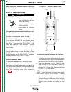
POWER SOURCE SETUP
Refer to the Instruction Manual provided with the Multi-
Source power source, or other DC power source being
used, for input power supply connections, output con-
nections and controls setup.
In general:
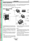
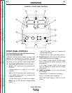
1. Connect the positive (+) output connection terminal
to the input supplying the Multi-Weld system and
the negative (-) output connection terminal to the
work. (See Figure A.1.)
2. If not using a Multi-Source power source:
a. If an inductance control, or tap, is selectable,
use lowest inductance.
b. Use CC (Constant Current) mode for maximum
supply voltage.
c. Set panel output control to maximum for maxi-
mum current capacity.
d. Activate output with the “output terminals on”
switch, or jumper (2-4 on Lincoln Electric termi-
nal strips).
A-6 A-6
INSTALLATION
MULTI-WELD 350
Return to Section TOC Return to Section TOC Return to Section TOC Return to Section TOC
Return to Master TOC Return to Master TOC Return to Master TOC Return to Master TOC
WARNING