


TROUBLESHOOTING & REPAIR
F-50 F-50
MULTI-WELD 350
Return to Section TOC Return to Section TOC Return to Section TOC Return to Section TOC
Return to Master TOC Return to Master TOC Return to Master TOC Return to Master TOC
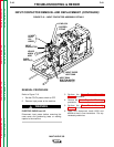
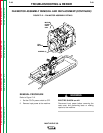
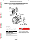
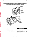
FAN MOTOR ASSEMBLY REMOVAL AND REPLACEMENT(CONTINUED)
3. Perform the Input Diode Removal proce-
dure.
4. Disconnect the red motor lead from leads
#303 and #303A and the blue motor lead
from lead #300 at their in-line connectors.
Cut any necessary cable ties.
5. Disconnect the two plug harness connec-
tions at the top of the tunnel assembly.
6. Using the phillips head screw driver,
remove the two screws holding the fan
motor housing to the tunnel assembly.
7. Carefully remove the fan motor assembly.
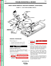
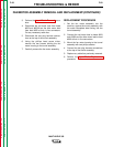
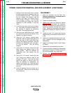
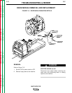
REPLACEMENT PROCEDURE
1. Set the fan motor assembly into the
machine, against the tunnel assembly, with
the motor nameplate label facing into the
tunnel assembly.
2. Connect the red motor lead to leads #303
and #303A and the blue motor lead to lead
#300 at their in-line connectors.
3. Mount the fan motor housing to the tunnel
assembly with two phillips screws.
4. Connect the two plug harness connections
at the top of the tunnel assembly.
5. Replace any cable ties previously removed.
6. Perform the Input Diode Replacement
procedure.