


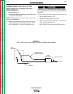


POWER MODULES AND FEED-
BACK
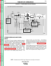
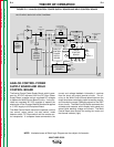
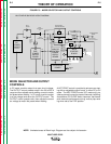
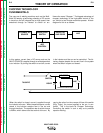
The external DC source voltage is applied to parallel
capacitors incorporated within each of the two Power
(Chopper) Modules. These capacitors function as fil-
ters and as power supplies for the IGBTs. See IGBT
Operation in this section. The IGBTs act as high-
speed switches operating at 20KHZ. These devices
are switched on and off by the Weld Control Board
through pulse width modulation gate signals. See
Pulse Width Modulation in this section. This
“chopped” DC output is applied through choke coils
and a shunt to the welding output terminals. The
chokes function as current filters. Free-wheeling
diodes are incorporated in the power circuit to provide
a current path for the stored energy in the chokes when
the IGBTs are turned off. See Chopper Technology in
this section.
Output voltage and current feedback information is fed
to the Weld Control Board. This information is sensed
from the output terminal circuits and the shunt. The
feedback information is processed by the Weld Control
Board, which regulates output voltage and current.
E-3 E-3
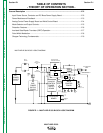
THEORY OF OPERATION
MULTI-WELD 350
Return to Section TOC Return to Section TOC Return to Section TOC Return to Section TOC
Return to Master TOC Return to Master TOC Return to Master TOC Return to Master TOC
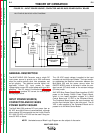
NOTE: Unshaded areas of Block Logic Diagram are the subject of discussion.
CHOKE
IGBT
IGBT
SHUNT
WORK
TO ELECTRODE
CABLE
+
ANALOG
CONTROL
POWER
SUPPLY
BOARD
WELD
CONTROL
BOARD
ARC
FORCE
CONTROL
OUTPUT
CONTROL
HOT
START
DC
BUS
POWER
SUPPLY
BOARD
FAN
+
DC
POWER
SOURCE
(EXTERNAL)
_
REMOTE
RECEPTACLE
INPUT
DIODES
INPUT
CONTACTOR
MULTI-WELD 350 BLOCK LOGIC DIAGRAM
CC SLOPE
(STICK/GOUGE or PIPE)
PERIPHERAL
BOARD
INPUT
INDICATOR
LIGHT
ON/OFF
MODE
SWITCH
(1/2)
CR1
CHOPPER MODULE
CHOPPER MODULE
ON/OFF
MODE
SWITCH
(1/2)
VOLTS
AMPS
THERMAL
LIGHT
FREEWHEELING DIODE
FREEWHEELING DIODE
REGULATED
VOLTAGES
CR1
COIL
15 VDC
CURRENT FEEDBACK
TO WELD CONTROL BOARD
20
VDC
x 2
-
INPUT
CAPACITORS
40
VDC
LEFT AND RIGHT
CHOPPER MODULES
GATE
SIGNALS
40 VDC
FIGURE E.3 – POWER MODULES AND FEEDBACK