


TROUBLESHOOTING & REPAIR
F-44 F-44
MULTI-WELD 350
Return to Section TOC Return to Section TOC Return to Section TOC Return to Section TOC
Return to Master TOC Return to Master TOC Return to Master TOC Return to Master TOC
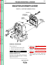
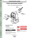
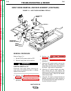
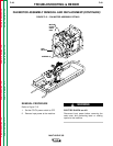
INPUT CONTACTOR REMOVAL AND REPLACEMENT (CONTINUED)
7. Using the 17 mm wrench, remove the nuts
from the input contactor terminal closest to
the machine front. Label the leads and
note their placement: bottom nut (not
removed), lead #X1A, Lead #X1, lead
#BP5.
NOTE: The top nut has grooves on the side that
faces up.
8. Using the 17 mm wrench, remove the nuts
from the other input contactor terminal.
Bottom nut (not removed), copper contac-
tor strap, center nut, lead #331, top nut.
NOTE: The top nut has grooves on the side that
faces up.
9. With the 3/8" socket wrench, remove the
two bolts and nylon insulators holding the
input contactor to the input diode heat sink.
NOTE: The mylar insulation sheet fits between
the nylon insulators at replacement.
10. Using the 3/8" socket wrench, remove the
two screws holding the input contactor to
the machine base.
11. Carefully remove the input contactor.
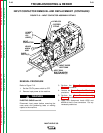
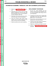
REPLACEMENT PROCEDURE
1. Set the input contactor onto the machine
base and install two 3/8" screws in the base
mounting holes.
2. Install the two sets of 3/8" bolts and nylon
insulators, along with the mylar insulation
sheet, to the input diode heat sink. The
mylar sheet fits between the nylon insula-
tors under the mounting bracket.
3. Install the copper contactor strap and lead
#331 to the input contactor rear terminal.
See Figure F.10.
4. Install leads #X1A, X1, and #BP5 to the
input contactor front terminal. See Figure
F.10. Be sure the top nut on each terminal
is the grooved nut, with the grooves facing
up.
5. Connect leads #330 and #303A at their in-
line connectors.
6. Replace any cable ties cut at disassembly.
7. Perform the Case Front Assembly
Replacement procedure.
8. Perform the Case Cover Assembly
Replacement procedure.