


TROUBLESHOOTING & REPAIR
F-52 F-52
MULTI-WELD 350
Return to Section TOC Return to Section TOC Return to Section TOC Return to Section TOC
Return to Master TOC Return to Master TOC Return to Master TOC Return to Master TOC
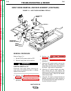
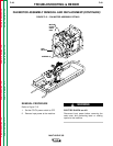
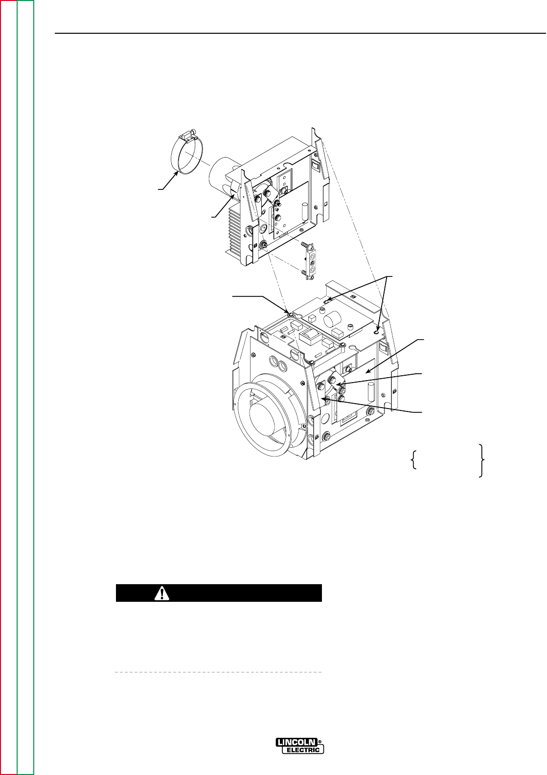
CLAMP
BRACKET
ANALOG CONTROL
SUPPLY PC BOARD
(4 SCREWS)
SCREWS (2)
CHOPPER
PC BOARD
CAPACITOR
POSITIVE
STRAP
CAPACITOR
NEGATIVE
STRAP
LEADS
+
-
RIGHT
SIDE
LEFT
SIDE
#X4A
#X1A
#X4
#X1
#401
#401A
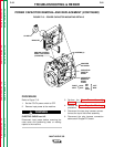
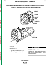
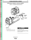
FIGURE F.13 – POWER CAPACITOR MOUNTING DETAILS
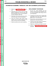
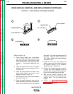
POWER CAPACITOR REMOVAL AND REPLACEMENT (CONTINUED)
PROCEDURE
Refer to Figure F.13.
1. Set the CC/CV power switch to OFF.
2. Remove input power to the machine.
ELECTRIC SHOCK can kill.
Disconnect input power before removing the
case cover and performing tests or making
repairs to the machine.
3. Perform the Case Cover Assembly
Removal procedure.
4. Perform the Power Capacitor Discharge
procedure.
5. Disconnect the two plug harness connec-
tions at the top of the tunnel assembly.
6. Disconnect the plug harness connection
above each Chopper PC board.
WARNING