


TROUBLESHOOTING & REPAIR
F-59 F-59
MULTI-WELD 350
Return to Section TOC Return to Section TOC Return to Section TOC Return to Section TOC
Return to Master TOC Return to Master TOC Return to Master TOC Return to Master TOC
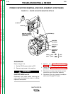
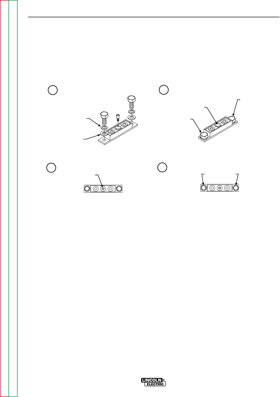
SPRING WASHER
PLAIN WASHER
2 TO 3
TURNS EACH
FINGER TIGHT
5.0-10 IN-LBS.
5.0-10 IN-LBS.
12-18 IN-LBS.
30-40 IN-LBS.
1
2
3
4
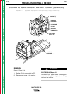
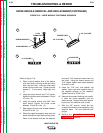
FIGURE F.16 – DIODE MODULE TIGHTENING SEQUENCE
DIODE MODULE REMOVAL AND REPLACEMENT(CONTINUED)
Refer to Figure F.16.
4. Place a spring washer then a flat washer
over each outer mounting screw and insert
them into the holes. Insert the allen head
screw into the center hole. Tighten all three
screws 2 – 3 turns each, finger-tight only.
(1)
5. Using the torque wrench and 7/16" socket,
tighten the outer screws to between 5.0 and
10 in-lbs. (2)
6. Using the torque wrench and 9/64" allen
head socket, tighten the center screw
between 12 and 18 in-lbs. (3)
7. Now tighten the two outer screws between
30 and 40 in-lbs. (4)
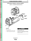
8. Place the negative capacitor strap over the
diode module and align the mounting holes.
Place a lock washer and two flat washers
over each 7/16" screw and insert them into
the holes. Using the torque wrench and
7/16" socket, tighten each screw between
30 and 40 in-lbs.
9. Install the 7/16" bolt, lock washer, flat
washer, heavy lead and negative strap to
the negative terminal on the capacitor.
Tighten the bolt to 50-60 in-lbs.
10. Remove the wooden blocking and careful-
ly lower the tunnel assembly onto the
machine base. Support the tunnel assem-
bly and turn the machine onto its side.
11. With the 3/8" wrench, install the four
screws that hold the tunnel assembly to the
machine base. Turn the machine back
upright.
12. Perform the Case Cover Assembly
Replacement procedure.