


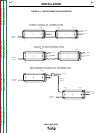
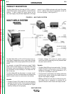
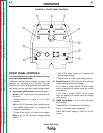
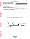

FRONT PANEL CONTROLS
The numbered items of Figure B.2 match the num-
bered items described below:
These few instruments and controls are basic to the
operation and monitoring of the Converter. They are
intuitively laid out so that the panel left side is weld cur-
rent related, and the right side is weld voltage related:
(1) Input Power/ Mode Switch has three positions:
Center is OFF, which shuts off input power to the
Converter.
• Neither displays nor output is on if in OFF
position.
Left is on for CC (constant current) welding mode.
• Only AMPS digital meter is lit, displaying the
preset current setting.
• Output will be on at o.c.v. (open circuit voltage).
Right is on for CV (constant voltage) welding
mode.
• Only VOLTS digital meter is lit, displaying the
preset voltage setting.
• Output will be on at the output voltage setting.
(2) Output Control has 3-3/4 turn resolution with slip-
clutch to prevent control pot damage.
In CC mode it presets AMPS (30-350A range)
when not welding and adjusts actual arc current
while welding.
In CV mode it presets VOLTS (15-40v range)
when not welding and adjusts actual arc voltage
while welding.
(3) AMPS Digital Meter is a 3-1/2 digit LED meter
which displays:
Preset AMPS in CC mode when not welding.
“Blank” in CV mode when not welding.
Actual AMPS while welding in both CC and CV
modes.
B-6 B-6
OPERATION
MULTI-WELD 350
Return to Section TOC Return to Section TOC Return to Section TOC Return to Section TOC
Return to Master TOC Return to Master TOC Return to Master TOC Return to Master TOC
1
2
3
4
5
6
7
8
9
10
INPUT
WORK
ELECTRODE
+
+
FIGURE B.2 – FRONT PANEL CONTROLS