


TROUBLESHOOTING & REPAIR
F-47 F-47
MULTI-WELD 350
Return to Section TOC Return to Section TOC Return to Section TOC Return to Section TOC
Return to Master TOC Return to Master TOC Return to Master TOC Return to Master TOC
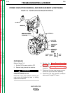
INPUT DIODE REMOVAL AND REPLACEMENT (CONTINUED)
10. Disconnect thermostat leads #306 and
#307.
11. Carefully remove the input diode assembly.
12. Using the 1
1
⁄4" wrench, loosen the appropri-
ate diode and remove the diode that is to
be replaced.
13. Clean the area on the heat sink around the
diode mounting surface using a putty knife
or similar tool. DO NOT SCRATCH THE
DIODE MOUNTING SURFACE.
14. Polish the heat sink’s mounting surface to
provide a bright, clean surface where the
diode seats on the heat sink. Wipe the sur-
face clean with a lint-free cloth or paper
towel.
15. Inspect the mounting surfaces of each new
diode. Remove all burrs and wipe clean.
Do not use steel wool or any abrasive
cleanser on the diode mounting surface.
16. Apply a thin (0.003" to 0.007") uniform
layer of Penetrox A13 joint compound to
the heat sink mounting surface.
17. Do not apply compound to the diode stud
or mounting threads.
18. Apply two drops of Loctite 271 to the diode
stud threads before tightening.
NOTE: The diode threads must be clean and
free of defects so that it can be finger tightened
before applying torque. A “slip” type torque
wrench must be used to tighten the diode.
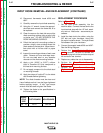
19. Tighten the diode to the specifications in
the following table.
DIODE
STUD FOOT-POUNDS INCH-POUNDS
SIZE
3/4 - 16 25-27 300-324
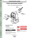
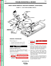
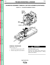
REPLACEMENT PROCEDURE
Refer to Figure F.11.
1. Set the input diode assembly into the
machine base. Connect the heat sink to the
input terminal strap with the 1/2" bolt, wash-
ers, and nut. Note order – see removal pro-
cedures.
2. Install the heat sink to the choke, using the
3/8" bolt and nylon insulators, along with
the mylar insulation sheet. The mylar sheet
fits between the nylon insulators.
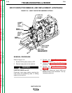
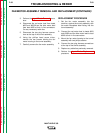
3. Connect thermostat leads #306 and #307.
See the Wiring Diagram.
4. Perform the Input Contactor Replace-
ment procedure. Be sure to connect the
input diode pig-tails to the contactor strap at
the contactor rear terminal.
5. Replace any cable ties cut at disassembly.
6. Perform the Case Front Assembly
Replacement procedure.
7. Perform the Case Cover Assembly
Replacement procedure.