


Read this entire installation section before you
start installation.
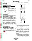
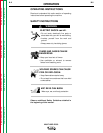
SAFETY PRECAUTIONS
ELECTRIC SHOCK can kill.
• Do not touch electrically live
parts or electrodes with your
skin or wet clothing.
• Insulate yourself from the
work and ground.
• Always wear dry insulating
gloves.
Only qualified personnel should install, use, or ser-
vice this equipment.
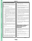
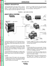
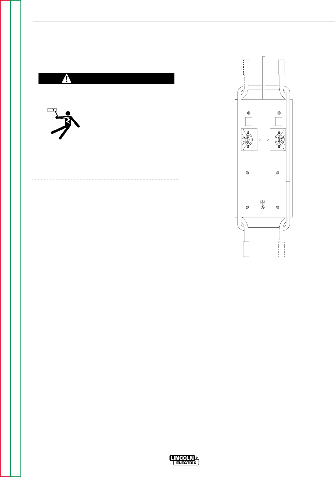
QUICK-CONNECT “PIG-TAILS”
The Multi-Weld 350 is factory provided with two 21
in.(53 cm) long 2/0 AWG (70 mm
2
) “pig-tail” cables.
Their 0.5" (13 mm) hole lug ends are routed through
the “INPUT +” (on back) and “ELECTRODE +” (on
front) cable channels of the Converter. They are
attached to the bottom-accessed covered cable con-
nection studs.
Attach the preferred standard, user-provided Quick-
connect terminal (such as Lincoln Twist-Mate or Tweco
2-MPC type) to the cut-off end of these cables. Use the
female connector on the “ELECTRODE +” cable and
the male connector on the “INPUT +” cable.
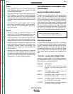
ATTACHMENT AND
ARRANGEMENT OF “PIG-TAILS”
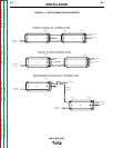
To best suit the desired inter-connection of the
Converters, the “pig-tail” cables may be routed into the
front or back cable channels. For single or double “pig-
tail” cables, route through the bottom-accessed cov-
ered cable connection studs. (See Figures A.1
and B.1.)
To connect the “pig-tail” cables to the Converter:
1. Stand the Converter vertically on its rear handle
and skid to gain access to the bottom stud covers.
Then remove the two 0.25"(6.3 mm) screws secur-
ing each cover and fold out the cover insulation.
2. Route the appropriate “pig-tail” cable lug ends
under the skid rail (for strain-relief) through the
desired front and/or rear corner channels to the
exposed 0.5" (13 mm) stud. Remove the flange
nut with a .75" (19 mm) wrench.
NOTE: Input supply cable(s) must connect through
“INPUT +” labeled channels, and output weld cable(s)
must connect through “ELECTRODE +” labeled
channels.
3. Slip the “pig-tail” cable lug(s) over the stud and re-
secure the flange nut. Make sure that the lug(s) do
not touch any sheetmetal of the stud housing. Fold
back the cover insulation and replace the stud
cover.
A-3 A-3
INSTALLATION
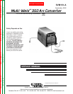
MULTI-WELD 350
Return to Section TOC Return to Section TOC Return to Section TOC Return to Section TOC
Return to Master TOC Return to Master TOC Return to Master TOC Return to Master TOC
WARNING
BOTTOM VIEW
TO ELECT.
TO ELECT.
TO
WORK
TO POWER
SOURCE
TO POWER
SOURCE
+
INPUT
+
ELECTRODE
ELECT.
+
ELECT.
+
+
IN
+
IN
FIGURE A.1 – PIG-TAIL CONNECTIONS