


TROUBLESHOOTING & REPAIR
F-25 F-25
MULTI-WELD 350
Return to Section TOC Return to Section TOC Return to Section TOC Return to Section TOC
Return to Master TOC Return to Master TOC Return to Master TOC Return to Master TOC
DC BUSS POWER SUPPLY PC BOARD TEST(CONTINUED)
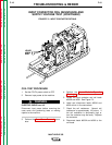
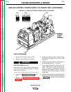
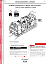
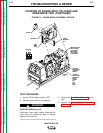
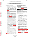
8. Check the DC Buss Power Supply PC
Board input and output voltages according
to Table F.2. See Figure F.5 and the
Wiring Diagram.
9. If all the voltages are correct, the DC Buss
Power Supply PC Board is operating prop-
erly.
10. If any of the output voltages are not correct
and the input voltage is correct, the DC
Buss Supply Board may be faulty.
11. If the input voltage is not correct, check
leads #401A, #402, #302, #202, #231 and
the On/Off mode switch (SW1). See the
Wiring Diagram.
NOTE: The input voltage to the DC Buss Power
Supply PC Board should be the same as the
input voltage applied to the Multi-Weld 350.
12. If finished testing, perform the Case Cover
Replacement procedure.
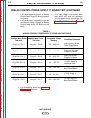
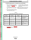
TABLE F.2
DC BUSS POWER SUPPLY PC BOARD VOLTAGE TABLE
Positive Meter Probe Negative Meter Probe Acceptable Voltage
Conditions/Comments
Test Point Test Point Reading
Plug P46 – Pin 1 Plug P46 – Pin 3 50 – 113 VDC
Should be same as input
voltage supplied to
Multi-Weld 350
Plug P47 – Pin 7 Plug P47 – Pin 1 38.0 – 42.0 VDC
Supply to Analog Control
Power Supply PC Board
Plug P47 – Pin 8 Plug P47 – Pin 6 38.0 – 42.0 VDC
Supply for Fan and Input
Contactor
Plug P47 – Pin 4 Plug P47 – Pin 6 38.0 – 42.0 VDC
Output to Peripheral
Board