


SAFETY PRECAUTIONS
ELECTRIC SHOCK can kill.
• Do not touch electrically live parts or
electrode with skin or wet clothing.
• Insulate yourself from work and ground.
• Always wear dry insulating gloves.
Have qualified personnel do the maintenance work.
Always use the greatest care when working near mov-
ing parts.
If a problem cannot be corrected by following the
instructions, take the machine to the nearest Lincoln
Field Service Shop.
See additional warning information throughout this
manual.
MAINTENANCE
The only maintenance that may be required for the
Multi-Weld 350 is to clean out any accumulated dirt and
debris. Clogging could contaminate internal compo-
nents or obstruct proper cooling of the power compo-
nents, resulting in premature over-temperature shut-
down.
The recommended cleaning procedure is as follows:
1. Be sure to disconnect the Converter input cable to
remove its input power.
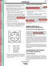
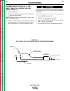
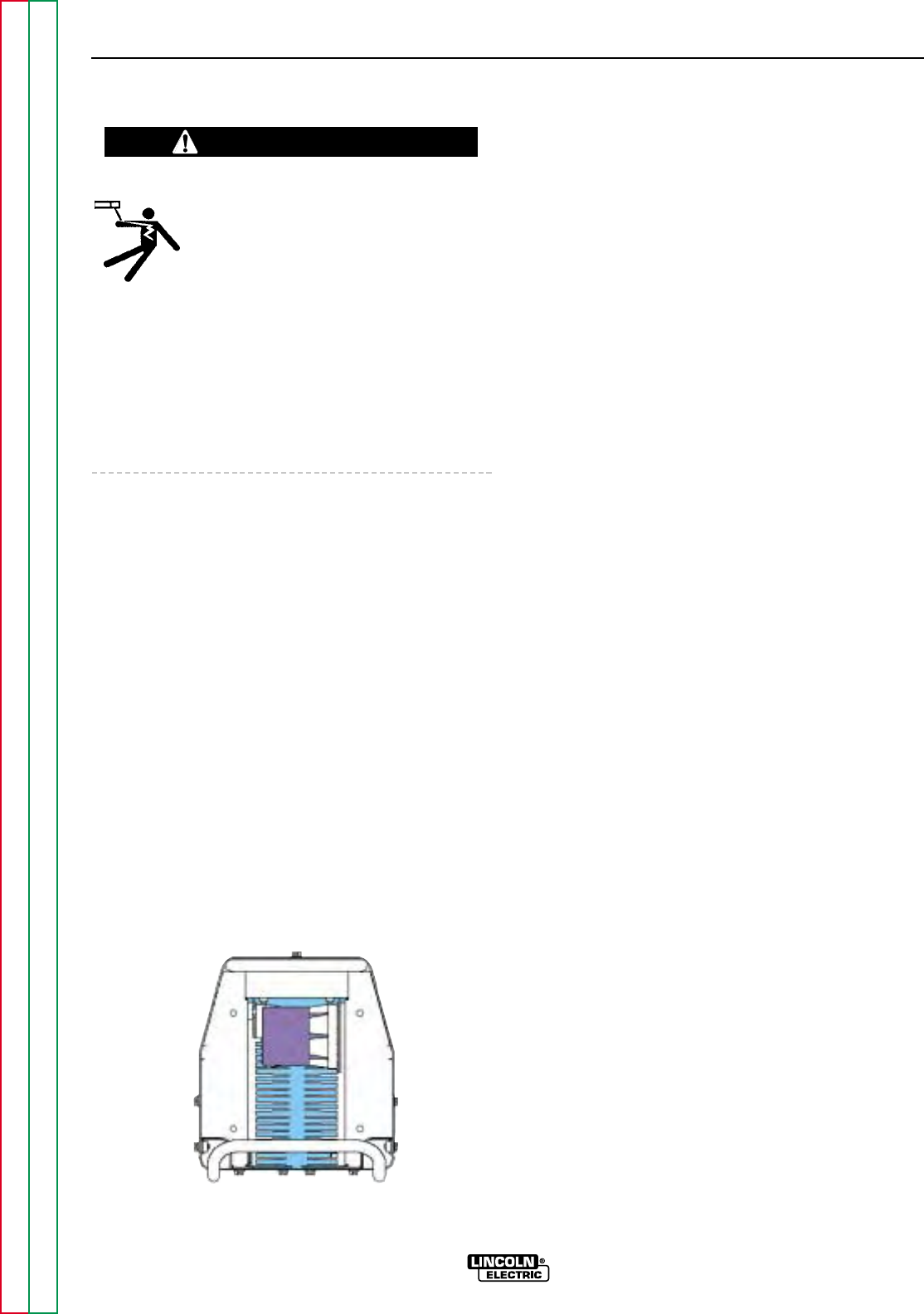
2. Remove the four screws securing the rear louver
panel and remove the panel to expose the cooling
tunnel heatsinks. (See Figure D.1 below.)
3. Holding the unit by the front handles, so the back is
facing down, shake the loose debris out of the unit.
Raking out the heatsink fins may be necessary for
jammed debris.
4. If necessary, remove the case wraparound cover.
Using the skid handles to hold the unit upside down,
carefully dump out any remaining loose debris or
carefully blow out using low pressure air.
5. Reassemble the cleaned out Converter by reversing
the above steps.
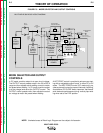
DIGITAL METER CALIBRATION
If calibration of either digital meter is ever necessary,
meter calibration adjustment trimmers are provided on
the Weld Control PC board inside the Control Module.
(See Figure D.2.) Calibration must be done with an
Output current load, so meters are displaying Actual
(not Preset) values. It is recommended that the cali-
bration levels be near the rating plate values, for best
accuracy, and compared to "master" meters with better
than 2% accuracy.
The accuracy of Actual AMPS meter should be within
3% of the welding amps monitored. The AMPS meter
trimmer (R561) is located near the center of the Weld
Control PC board just below the VOLTS meter trimmer
(R562). Clockwise rotation of the trimmer adjustment
screw will decrease the meter reading.
The accuracy of Actual VOLTS meter should be within
3% of the welding volts monitored. The VOLTS meter
trimmer (R562) is located near the center of the Weld
Control PC board just above the AMPS meter trimmer
(R561). Clockwise rotation of the trimmer adjustment
screw will decrease the meter reading. The “master”
voltmeter should be connected as close as possible to
the “ELECTRODE +” stud and “WORK -” lead bolt for
best accuracy.
D-2 D-2
MAINTENANCE
MULTI-WELD 350
Return to Section TOC Return to Section TOC Return to Section TOC Return to Section TOC
Return to Master TOC Return to Master TOC Return to Master TOC Return to Master TOC
WARNING
FIGURE D.1 – TUNNEL HEATSINKS