


TROUBLESHOOTING & REPAIR
F-53 F-53
MULTI-WELD 350
Return to Section TOC Return to Section TOC Return to Section TOC Return to Section TOC
Return to Master TOC Return to Master TOC Return to Master TOC Return to Master TOC
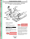
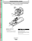
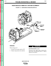
POWER CAPACITOR REMOVAL AND REPLACEMENT (CONTINUED)
7. Using the slot head screw driver, remove
the two screws and lock washers from the
tunnel assembly top cover. Then remove
the four screws, lock washers, and flat
washers that mount the Analog Control
Power Supply PC Board. This will allow
you to access the clamps that hold the
capacitors to their brackets in the heat
sinks.
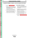
8. Lift off the top cover of the tunnel assem-
bly. Peel away the adhesive-backed rub-
ber stripping (if present) as necessary.
Use care – the stripping may tear.
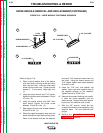
9. Using the slot head screw driver, loosen
the clamp from around the bracket of the
capacitor you want to remove.
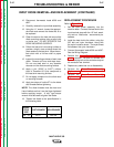
10. Using the 7/16" wrench, remove heavy
leads #X1, #X4 and small leads #401 and
401A (left side) or #X1A and #X4A (right
side) of the capacitor terminals. Note the
fasteners for reassembly: bolt, lock wash-
er, and flat washer. See the Wiring
Diagram.
11. Using the 7/16" wrench, remove the two
bolts holding the negative strap to the
diode module. Note the fasteners for
reassembly: bolt, lock washer, two flat
washers.
12. Using the 7/16" wrench, remove the two
nuts holding the positive strap to the
Chopper PC board. Hold the bolt head
behind the board to remove each nut.
Note the fasteners for reassembly: flat
washer, lock washer, nut. Note the place-
ment of the reverse diode lead on the bot-
tom bolt.
13. Push the capacitor from the inside, out of
the heat sink. Note that the bracket stays
in the heat sink.
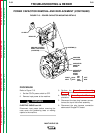
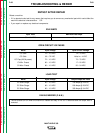
REASSEMBLY
1. Slide the capacitor into the heat sink.
Position the positive (+) terminal next to
the Chopper PC board.
2. Tighten the bracket clamp.
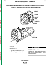
3. Replace the leads and straps as labeled
(Figure F.13) and tighten the fasteners.
Use the 7/16" socket and torque wrench to
tighten the capacitor terminal bolt to 50-60
in-lbs. Tighten the nuts holding the positive
strap to the Chopper PC board to 50-60 in-
lbs.
4. Tighten the two 7/16" screws that hold the
negative strap to the diode module to 30-40
in-lbs.
5. Replace any adhesive-backed rubber strip-
ping, if present, that was damaged during
disassembly.
6. Replace the Analog Control Power Supply
PC Board.
7. Replace the tunnel assembly top cover.
8. Connect the wire harness plug assemblies
above each Chopper PC Board and above
the tunnel assembly (four plugs total).
9. Perform the Case Cover Assembly
Replacement procedure.