


SERVICE
The Multi-Weld 350 was designed for easy service
using quick-to-replace components and assembly
modules that can be simply swapped out at the job site
to minimize down time. More prolonged troubleshoot-
ing and repair of the module may be done later on the
service bench.
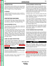
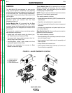
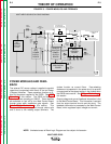
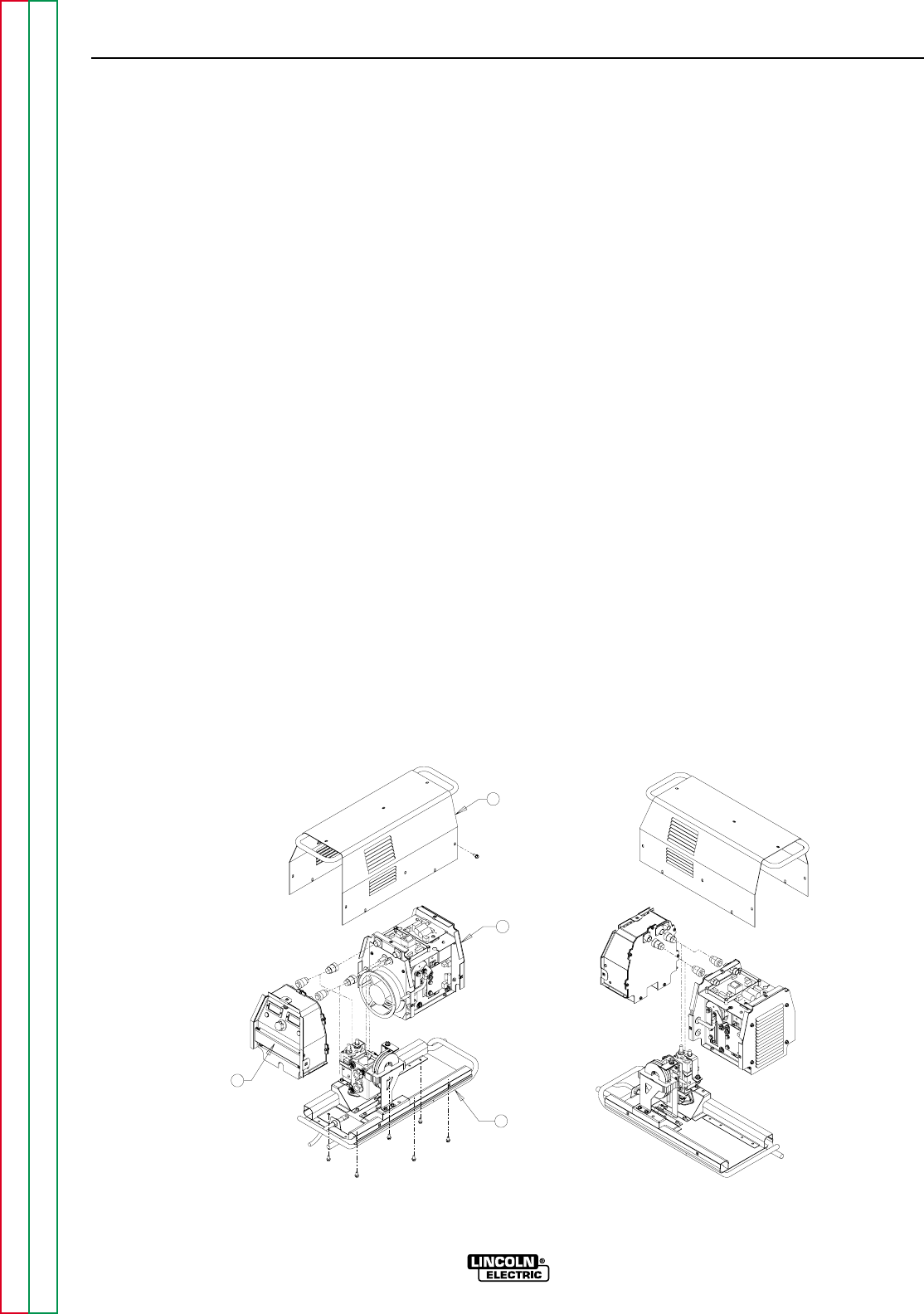
Figure D.2 shows the three assembly modules of the
Converter which are covered with the Case
Wraparound (item (4):
Control Module (item (1) is removed from the Base
Module assembly by removing the two bottom
accessed screws and disconnecting the three sealed
harness plugs from the receptacles on the back of the
Control box.
This module is a sealed enclosure containing replace-
able electronic components:
• Sealed back cover which mounts the internal “pot-
ted” Weld Control and Peripheral PCBs.
• Front panel with “plug-n-play” instruments that indi-
vidually plug to the Control PCB.
• Interchangeable “potted” digital meters with front
replaceable spatter shield lenses.
• Harness lead receptacles that connect to Base
Module harness lead plugs.
Tunnel Module (item (2) is removed from the Base
Module assembly by removing the four bottom
accessed screws and disconnecting the two sealed
harness plugs and power leads.
NOTE: Removal of Control Module improves access to
disconnect Tunnel Module power leads.
This module assembly includes:
• Heatsinked power switching (IGBT) boards and iso-
lated diodes.
• Capacitors and potted power supply boards.
• Fan and sheetmetal bulkhead tunnel and component
enclosure.
• Harness lead receptacles and power leads that con-
nect to Base Module.
Base Module (item (3) is the mounting and connection
platform for the other modules.
This module assembly includes:
• Base sheetmetal with input/output connection cham-
bers with "pigtail" leads.
• Input contactor, input diodes heat sink assembly and
Work clip lead.
• Output chokes and current shunt.
• Lead harness sealed plugs connect to Tunnel and
Control Module receptacles.
D-3 D-3
MAINTENANCE
MULTI-WELD 350
Return to Section TOC Return to Section TOC Return to Section TOC Return to Section TOC
Return to Master TOC Return to Master TOC Return to Master TOC Return to Master TOC
2
4
1
3
FIGURE D.2 – MAJOR COMPONENT LOCATIONS
1. CONTROL MODULE
2. TUNNEL MODULE
3. BASE MODULE
4. CASE WRAPAROUND