


TROUBLESHOOTING & REPAIR
F-47 F-47
COMMANDER 500
Return to Section TOC Return to Section TOC Return to Section TOC Return to Section TOC
Return to Master TOC Return to Master TOC Return to Master TOC Return to Master TOC
W10
W9
DIODE
LEAD D4
TEMPERATURE
SWITCH
POWER
MODULE
PC BOARD
POSITIVE (+)
STRAP
POSITIVE (+)
STRAP
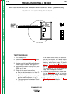
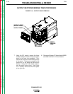
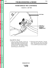
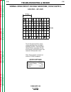
FIGURE F.21 – POWER MODULE CAPACITOR LEADS (LEFT SIDE)
POWER MODULE TEST (CONTINUED)
TEST PROCEDURE
1. Turn the engine off.
2. Perform the Case Cover Removal proce-
dure.
3. Perform the Power Module Capacitor
Discharge procedure.
4. Using the 7/16" wrench, loosen the nuts on
the positive terminals of the power capaci-
tors. Then remove the nuts, lock washers,
and flat washers from the terminals where
the positive straps connect to the power
module PC board. Flip the straps out of the
way. Also remove diode lead D3 (if working
on right side power module) or D4 (if work-
ing on left side power module). See Figure
F.21.
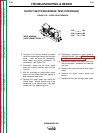
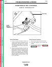
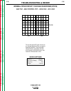
5. Using the 7/16" wrench, remove the flex
leads W9 and W10 (left side) or W7 and W8
(right side) from the Power Module PC board
terminals.
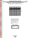
6. Using the 7/16" wrench, remove the nega-
tive jumper strap attaching the power capac-
itors to the Power Module PC board.
NOTE: Make sure the bolts do not fall back
against the heat sink.