


TROUBLESHOOTING & REPAIR
F-76 F-76
COMMANDER 500
Return to Section TOC Return to Section TOC Return to Section TOC Return to Section TOC
Return to Master TOC Return to Master TOC Return to Master TOC Return to Master TOC
#200A
#200B
#201
12 VDC STUD
LEADS #232L
AND #232M
PULL COIL PC BOARD
(LEADS #265 AND #227)
CONTROL BOX
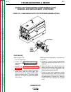
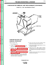
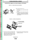
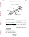
FIGURE F.35 – BRUSH HOLDER AND LEAD REMOVAL
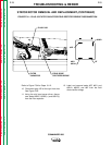
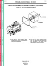
FIGURE F.36 – CONTROL BOX CONNECTIONS
STATOR/ROTOR REMOVAL AND REPLACEMENT (CONTINUED)
Refer to Figure F.35 for Steps 13-15.
13. Using the 3/8" wrench, remove the brush holder
access panel.
14. Using the 3/8" wrench, remove the brush holder
assembly.
15. Cut the cable tie and then label and remove brush
leads #201(-) and piggy-backed leads #200A(+)
and #200B(+) from the brush holder assembly.
(The piggy-backed leads connect closest to the
stator laminations.)
16. See Figure F.36. Disconnect leads #265 and #227
from the Pull Coil PC board. With the 7/16"
wrench, remove the nut, lock washer, and flat
washer from the 12 VDC insulated stud. Remove
leads 232L and #232M from the stud. Cut any
necessary cable ties. Pull all leads freed in this
step through the control box panel.
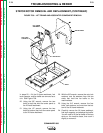
17. With the 3/8" wrench, remove the two screws from
the bottom of the control box. Swing the control
box aside and lay it down.