


TROUBLESHOOTING & REPAIR
F-79 F-79
COMMANDER 500
Return to Section TOC Return to Section TOC Return to Section TOC Return to Section TOC
Return to Master TOC Return to Master TOC Return to Master TOC Return to Master TOC
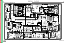
BOLTS
(4)
FAN HUB
MOUNTING
FOOT
FLYWHEEL
SPLASH
PLATE
FAN
NUT
STATOR / ENGINE
MOUNTING BOLTS &
LOCK WASHERS
BEARING
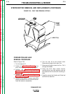
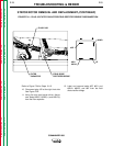
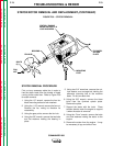
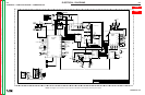
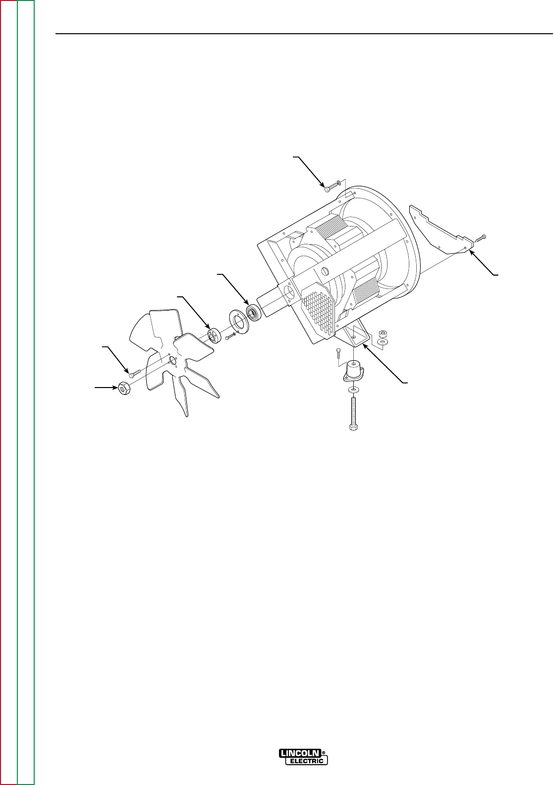
FIGURE F.39 – STATOR REMOVAL
STATOR/ROTOR REMOVAL AND REPLACEMENT (CONTINUED)
STATOR REMOVAL PROCEDURE
First, cut any necessary cable ties in order to
free the stator leads from the bundle of leads
running to the control box. Refer to Figure F.39
for stator removal.
1. Using the 1/2” wrench, remove the four fan
blade mounting bolts and lock washers.
2. Using the 1 1/8" wrench, remove the fan nut.
Remove the fan, noting its direction for
reassembly.
3. Using the gear puller, remove the fan hub.
4. Using the 3/8" wrench, remove the two bolts
and flat washers holding the bearing in
place.
5. Using two 3/4" wrenches, remove the nut,
lock washer, and carriage bolt holding the
alternator mounting foot to the machine
base. Do this on each side.
6. Using the 3/8" wrench, remove the three
bolts from the flywheel splash plate.
Remove the plate.
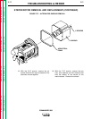
7. Support the stator with the hoist. Place
wooden blocks under the engine to support
it when the stator is removed.
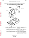
8. Using the 17mm" wrench, remove the bolts
and lock washers holding the stator to the
engine.
9. Remove the stator from the engine. It may
be necessary to pry and slide it free.