


TROUBLESHOOTING & REPAIR
F-48 F-48
COMMANDER 500
Return to Section TOC Return to Section TOC Return to Section TOC Return to Section TOC
Return to Master TOC Return to Master TOC Return to Master TOC Return to Master TOC
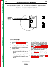
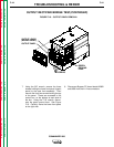
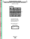
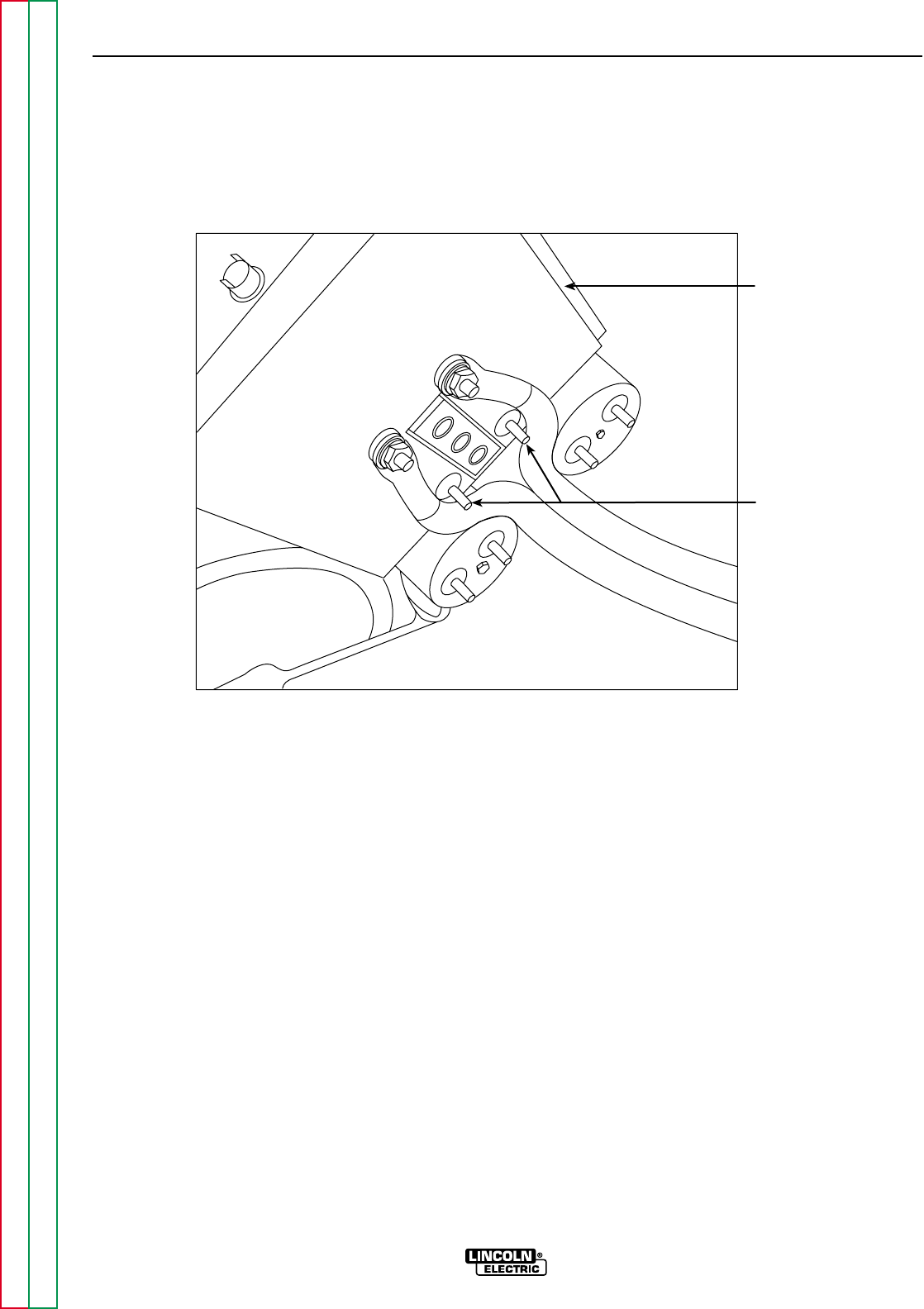
HEAT SINK
POSITIVE (+)
CAPACITOR
TERMINAL
CONNECTIONS
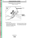
FIGURE F.22 – IGBT TEST
POWER MODULE TEST (CONTINUED)
Check IGBT For "Shorts"
7. Using the analog ohmmeter, connect the
positive meter probe to the heat sink and the
negative meter probe to the positive capaci-
tor terminal on the Power Module PC board.
See Figure F.22. The resistance reading
should be high (over 20,000 ohms).
8. Reverse the meter probe leads. The resis-
tance should be very high (over 50,000
ohms). It the resistance is low in either Step
7 or 8, the IGBT may be shorted or leaky.