


TROUBLESHOOTING & REPAIR
F-68 F-68
COMMANDER 500
Return to Section TOC Return to Section TOC Return to Section TOC Return to Section TOC
Return to Master TOC Return to Master TOC Return to Master TOC Return to Master TOC
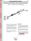
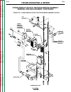
POWER MODULE (CHOPPER) PC BOARD/DIODE
MODULE REMOVAL AND REPLACEMENT (CONTINUED)
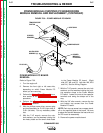
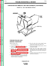
POWER MODULE PC BOARD
REPLACEMENT
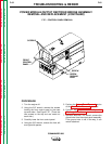
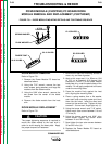
1. Apply Penetrox A-13 joint compound
(T12837-1) to the surface of the heat sink
where the Power Module PC board mounts.
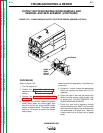
2. Install the top and bottom allen head cap
screws. Insert the bolts into the board
before mounting it. Torque the screws to 50-
60 inch-pounds.
IMPORTANT: Each top cap screw has a copper
standoff on the opposite side of the board. Be
sure to place this standoff between the heat
sink and the PC board.
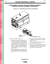
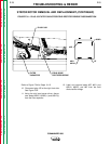
3. Install the positive capacitor straps, flat
washers, lock washers, and nuts. Torque
the nuts to 50-60 inch-pounds at the Power
Module PC board and at the capacitor termi-
nals.
4. Install the small diode leads and the heavy
leads, flat washers, lock washers, and nuts
to the Power Module PC board. Torque the
nuts to 50-60 inch-pounds.
5. Install plug and lead assembly P/J50 (right
side) or P/J51 (left side).
6. Replace any cable ties cut at disassembly.
See the procedures below for removal and
replacement of the Power Module PC board
diode module. When procedures are complete,
perform the Output Panel Replacement and
the Case Cover Replacement Procedures.