


TROUBLESHOOTING & REPAIR
F-71 F-71
COMMANDER 500
Return to Section TOC Return to Section TOC Return to Section TOC Return to Section TOC
Return to Master TOC Return to Master TOC Return to Master TOC Return to Master TOC
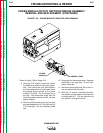
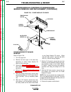
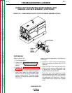
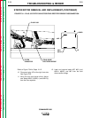
HEATSINKS
DIODE
DIODE
PIGTAIL
LEADS
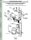
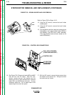
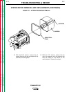
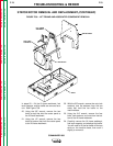
FIGURE F.32 – POWER MODULE/OUTPUT RECTIFIER BRIDGE ASSEMBLY DETAILS
OUTPUT RECTIFIER BRIDGE DIODE REMOVAL AND
REMOVAL AND REPLACEMENT (CONTINUED)
PROCEDURE
Refer to Figure F.32.
1. Turn the engine off.
2. Perform the Output Panel Removal as
described in the Case Cover Removal pro-
cedure.
3. Perform the Power Module Capacitor
Discharge procedure.
4. Using the 7/16" wrench, remove the appro-
priate stator leads and diode pigtail lead
from the stud on the output rectifier bridge
glastic insulator bracket. The bottom diodes
require a 1/2" wrench to remove the double
heavy leads.
Label the leads for reassembly if more than one
is removed.
5. Using the 1" wrench, loosen the appropriate
diode and remove the diode that is to be
replaced.
6. Clean the area on the heat sink around the
diode mounting surface using a putty knife
or similar tool. DO NOT SCRATCH THE
DIODE MOUNTING SURFACE.
7. Polish the heat sink's mounting surface
using an abrasive disc, E2827-2 or fine steel
wool to provide a bright, clean surface where
the diode seats on the heat sink. Wipe the
surface clean with a lint-free cloth or paper
towel.