


TROUBLESHOOTING & REPAIR
F-72 F-72
COMMANDER 500
Return to Section TOC Return to Section TOC Return to Section TOC Return to Section TOC
Return to Master TOC Return to Master TOC Return to Master TOC Return to Master TOC
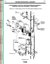
OUTPUT RECTIFIER BRIDGE DIODE REMOVAL AND
REMOVAL AND REPLACEMENT (CONTINUED)
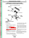
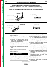
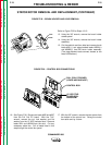
8. Inspect the mounting surfaces of each new
diode. Remove all burrs and wipe clean.
Do not use steel wool or any abrasive
cleanser on the diode mounting surface.
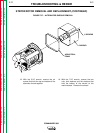
9. Apply a thin (0.003" to 0.007") uniform
layer of Penetrox A13 joint compound
(T12837-1) to the heat sink mounting sur-
face.
a. Do not apply compound to the diode
stud or mounting threads.
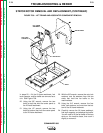
b. Apply two drops of Loctite 271 to the
diode stud threads before tightening.
NOTE: The diode threads must be clean and
free of defects so that it can be finger tightened
before applying torque. A "slip" type torque
wrench must be used to tighten the diode.
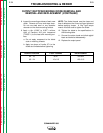
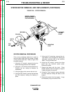
10. Tighten the diode to the specifications in
the following table.
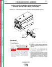
11. Connect the stator leads and diode pigtail
leads as labeled at disassembly.
12. Replace the output panel.
DIODE STUD SIZE FOOT POUNDS INCH POUNDS
3/4 - 16 25-27 300-324
3/8 - 24 10 ± 0.5 125 +0/-5