


TROUBLESHOOTING & REPAIR
F-20 F-20
COMMANDER 500
Return to Section TOC Return to Section TOC Return to Section TOC Return to Section TOC
Return to Master TOC Return to Master TOC Return to Master TOC Return to Master TOC
POWER
MODULE
CAPACITOR
TERMINALS
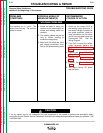
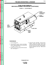
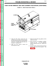
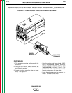
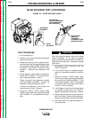
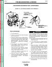
FIGURE F.4 – POWER MODULE CAPACITOR TERMINAL DISCHARGE
POWER MODULE CAPACITOR DISCHARGE PROCEDURE (CONTINUED)
PROCEDURE
1. This procedure must be performed with the
engine off.
2. Using the 3/8" wrench, remove the front left
and right side panels.
3. Locate the four capacitors (two on each
side). See Figure F.4.
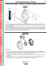
4. Using the resistor and jumper leads, CARE-
FULLY discharge the capacitor terminals.
NEVER USE A SHORTING STRAP FOR
THIS PURPOSE. DO NOT TOUCH THE
TERMINALS WITH YOUR BARE HANDS.
Repeat procedure on the other side.
5. Check the voltage across the capacitor ter-
minals. It should be zero volts.