


TROUBLESHOOTING & REPAIR
F-67 F-67
COMMANDER 500
Return to Section TOC Return to Section TOC Return to Section TOC Return to Section TOC
Return to Master TOC Return to Master TOC Return to Master TOC Return to Master TOC
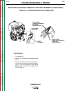
PLUG J50
ALLEN HEAD
SCREWS (4)
COPPER
SPACERS
TEMPERATURE
SWITCH
HEAT SINK
POWER
MODULE
PC BOARD
DIODE MODULE
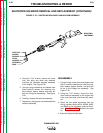
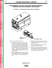
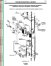
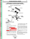
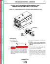
FIGURE F.30 – POWER MODULE PC BOARD
POWER MODULE (CHOPPER) PC BOARD/DIODE
MODULE REMOVAL AND REPLACEMENT (CONTINUED)
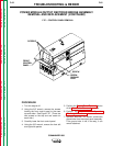
POWER MODULE PC BOARD
REMOVAL
Refer to Figure F.30.
1. Turn the engine off.
2. Remove the front right or left case side,
depending on which Power Module PC
board you are removing.
3. Perform the Output Panel Removal proce-
dure section of the Case Cover Removal
procedure.
4. Perform the Power Module Capacitor
Discharge procedure.
5. With the phillips screw driver, remove plug
and lead assembly for P/J 50 (right side) or
P/J51 (left side). Cut any necessary cable
ties.
6. With the 7/16" wrench, remove the nuts,
lock washers, and flat washers holding the
two heavy leads and the small diode leads
to the Power Module PC board. (Right
side: W7, W8, and D3. Left side: W9, W10
and D4.) See the Wiring Diagram.
7. With the 7/16" wrench, remove the nuts, lock
washers, and flat washers holding the posi-
tive capacitor straps to the Power Module
PC board. Loosen the nuts at the capacitor
terminals and swing the straps out of the
way.
8. With the 3/8" allen wrench, remove the top
and bottom cap screws from the Power
Module PC board.
NOTE: Each top cap screw has a copper stand-
off on the opposite side of the board. Be sure
to place this standoff between the heat sink and
the PC board at reassembly.
9. Remove the power module board.