


Observe Safety Guidelines TROUBLESHOOTING GUIDE
detailed in the beginning of this manual.
CAUTION
If for any reason you do not understand the test procedures or are unable to perform the test/repairs safely,
contact the Lincoln Electric Service Department for electrical troubleshooting assistance before you proceed. Call
1-800-833-9353.
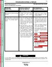
PROBLEMS
(SYMPTOMS)
POSSIBLE AREAS OF
MISADJUSTMENT(S)
RECOMMENDED
COURSE OF ACTION
OUTPUT PROBLEMS
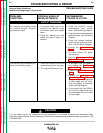
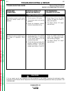
The machine has welding output
but no control of output. The auxil-
iary power is normal.
1. If a remote control unit is con-
nected to the machine, check
the remote control and related
cable.
2. Check the welding and work
cables for loose or faulty con-
nections.
1. Check the OUTPUT control
potentiometer and related
leads. See the Wiring Diagram.
2. Check the shunt and associated
feedback leads. See the Wiring
Diagram.
3. Check the voltage feedback
leads for loose or faulty connec-
tions. See the Wiring Diagram.
4. Perform the Power Module
Test.
5. The Weld Control PC board
may be faulty.
5. See the Start-Up and OCV
Diagnostic Chart.
F-6 F-6
TROUBLESHOOTING & REPAIR
COMMANDER 500
Return to Section TOC Return to Section TOC Return to Section TOC Return to Section TOC
Return to Master TOC Return to Master TOC Return to Master TOC Return to Master TOC
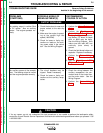
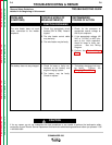
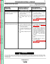
The machine has low welding out-
put and low auxiliary output.
1. Check the brushes for wear and
proper contact to the slip rings.
2. The engine RPM may be low.
1. If the engine high idle speed is
low, perform the Throttle Ad-
justment Test.
2. Perform the Rotor Resistance
Test.
3. Perform the Flashing and
Rotor Voltage Test. If the rotor
voltage is low, the field capacitor
or field bridge may be faulty.
Test and replace if necessary.
See the Wiring Diagram.
4. If the engine high idle RPM is
OK, then the engine may have
lost horsepower and be in need
of major repair.