


Return to Section TOC Return to Section TOC Return to Section TOC Return to Section TOC
Return to Master TOC Return to Master TOC Return to Master TOC Return to Master TOC
TROUBLESHOOTING & REPAIR
F-14
COMMANDER 500
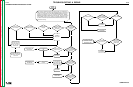
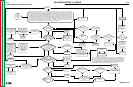
START-UP AND OCV DIAGNOSTIC CHART
F-14
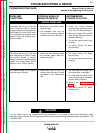
No LOW IDLE. Is
AUX current flowing?
TWO displays
illuminated?
Is WELD current
flowing?
Are J4 & 5
plugged
in properly?
Do you have AUX.
voltage?
In TIG Mode, do you
have proper OCV?
Is the A meter or
V meter illuminated?
Did the
ROTOR flash?
Is only ONE display
illuminated?
Does
the display inc./
dec. smoothly with the
Control Pot rotation?
Does it change?
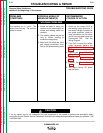
With the
WELDING TER. SW.
in“WELD TERM. ON” did unit go
to HI IDLE/back to LO and is there
OCV present at WELD
TERMINALS?
With the
WELD. TER. SW in
“REM. CONT.” and IDLER SW.
in “AUTO”, do you have 0-8V OCV
in all modes and go
to LOW IDLE?
In CV Mode, do you
have proper OCV?
In CC Mode, do you
have proper OCV?
Go to
Engine
Starting
Diagnostic
Chart
Start
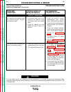
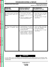
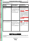
Upon starting the engine, there should be only ONE display illuminated (depending on which mode the machine is
in). The numbers in the display should increase/decrease smoothly and in a “linear” fashion with the rotation of
the Control (10K)Pot. Place the WELDING TERMINALS SW. In the “REMOTELY CONTROLLED” position and
place the IDLER SW. in the “AUTO” position. After about 12 seconds, the engine should go to LOW IDLE. Then
place the WELDING TERMINALS SW. in the “WELD TERMINALS ON” position. Engine should go back to HIGH
IDLE for 12 seconds and back to LOW IDLE and remain there. With the machine in CV Mode, you should have
an OCV range 23.7-25.2V at Min. and 75.0-78.0V at Max. In CC Mode, you should have an OCV range of 77-80V.
This WILL NOT change with the rotation of the Control Pot. In TIG Mode, you should have an OCV range of 11.0-
15.0V at Min. and 13.0-17.0V at Max. There is no need to check the PIPE OCV.
Y
Y
Y
Y
Y
CORRECT
that problem.
CORRECT
that problem.
CORRECT
that problem.
CORRECT
that problem.
CORRECT
that problem.
CORRECT
that problem.
CORRECT
that problem.
OCV too high.
CORRECT
that problem.
The numbers
“jump” as you turn
the Control Pot.
The Pot may be
bad.
The numbers DO
NOT change.
Check the Amphenols.
Insure nothing is
plugged into them. Also
check for excessive
tracking or corrosion of
the Amphenol.
Check the CONTROL
POT continuity and
continuity of wires 75,
76 & 77.
OCV is between 9-20V
in all modes. If so,
place a LIGHT load
(about 1/4 amp) across
the WELD TERM. If
the voltage goes away,
Chopper has some
slight leakage.
Continue.
OCV is higher, 70V or
more. Check
CHOPPER for a short
by unplugging J50 &
J51. This turns the
CHOPPER off. If OCV
still exists, then
CHOPPER must be
shorted or wired wrong.
No OCV. Check
CHOPPER and wires
15, 16, 17, 18, 23, 25,
23A and 25A.
No HIGH IDLE.
Check the WELD.
TERM. SW. Check
wires 2 & 4.
CORRECT
that problem.
CORRECT
that problem.
CORRECT
that problem.
CORRECT
that problem.
ANALOG POWER
SUPPLY MAY BE
BAD.
CONTROL PCB MAY
BE BAD.
N
N
N
N
OK
CONTROL PCB MAY
BE BAD.
CONTROL PCB MAY
BE BAD.
ANALOG POWER
SUPPLY MY BE BAD.
N
OK
N
N
Check for short on
any STATOR
winding. Check
WELD BRIDGE for
shorts.
Check BRUSHES,
BATTERY PCB
and wires 200,
200B, 200C, 200A,
200E, 201, 201A,
201B and 5L.
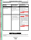
No LOW IDLE. Check Idle
Solenoid (.3 ohms for PULL
COIL and 21 ohms for
HOLD COIL) and wires 232L
& 227; 232S & 226A. Also
check mechanical linkage
going to Idle Solenoid.
Check VOLTAGE
FEEDBACK wire 208B.
Then NO displays
are illuminated.
Check wires 13 & 14.
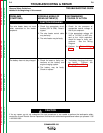
(NOTE: Under some circumstances, the CONTROL PCB can become defective in
such a way that it causes the ANALOG POWER SUPPLY (APS) to stop working and
visa versa. If you replace the APS, it may be suggested to replace the Control PCB
too. Inspect BOTH boards. If you notice any signs of over-heated or burnt compo-
nents on either board, replace BOTH boards together. IF YOU CHANGE ANY CIR-
CUIT BOARDS, START FROM THE BEGINNING OF THIS TEST.
N
N
Y
Y
N
Y
Y
N
N
N
N
CORRECT
that problem.
OK
V meter
N
CONTROL PCB MAY
BE BAD.
OK
Check the MODE
SELECT rotary switch
and wires 214, 218, 220
& 222.
Y
OK
A meter
Y
OK
N