


TROUBLESHOOTING & REPAIR
F-33 F-33
COMMANDER 500
Return to Section TOC Return to Section TOC Return to Section TOC Return to Section TOC
Return to Master TOC Return to Master TOC Return to Master TOC Return to Master TOC
FILTER
CAPACITOR
FIELD
DIODE
RECTIFIER
BRIDGE
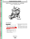
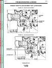
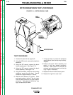
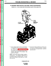
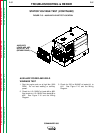
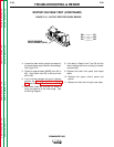
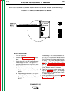
FIGURE F.12 - FIELD DIODE RECTIFIER BRIDGE AND FILTER CAPACITOR
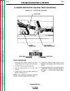
FLASHING AND ROTOR VOLTAGE TEST(CONTINUED)
7. If the voltage reading is low or not present,
the generator field is not functioning proper-
ly. Perform the Rotor Resistance Test.
Also check the field diode rectifier bridge, fil-
ter capacitor, and associated leads and con-
nections. See Figure F.12 for location. See
the Wiring Diagram.
NOTE: The normal flashing voltage is approxi-
mately 9VDC. This is battery voltage, which is
processed through the Battery board. This volt-
age must be present during start-up to "flash"
the rotor field.
8. If the rotor voltage readings are normal, the
field circuit is functioning properly. Replace
any cable ties cut during the test. Install the
right case side.