


TROUBLESHOOTING & REPAIR
F-65 F-65
COMMANDER 500
Return to Section TOC Return to Section TOC Return to Section TOC Return to Section TOC
Return to Master TOC Return to Master TOC Return to Master TOC Return to Master TOC
POWER MODULE/OUTPUT RECTIFIER BRIDGE ASSEMBLY
REMOVAL AND REPLACEMENT (CONTINUED)
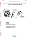
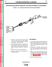
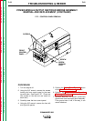
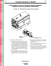
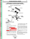
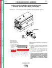
Refer to Figure F.29 for Steps 13-15.
13. Using the 7/16" wrench, remove the stator
"W" leads from the three terminals on the
plastic insulator bracket of the rectifier
bridge. Label the leads for reassembly.
Pull the leads out through the power mod-
ule top bracket.
14. Using the 1/2" wrench, remove the flat
strap to the negative output terminal. Pull
the strap through the power module top
bracket.
15. With the 7/16" socket wrench, remove the
four nuts, lock washers, flat washers, and
carriage bolts that hold the power module
bottom bracket to the machine base.
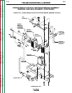
The power module/output rectifier bridge
assembly can now be removed and set to the
side.
REPLACEMENT PROCEDURE
1. Place the assembly back into the machine.
2. Install the four carriage bolts, flat washers,
lock washers, and nuts that hold the bottom
bracket to the machine base.
3. Pull the flat negative output strap through
the top bracket and attach it.
4. Feed the stator "W" leads through the top
bracket and attach them to the terminals on
the glastic insulator bracket.
5. Pass choke lead W11 through the toroid
and connect it to the shunt.
6. Connect plug assemblies P/J50 and P/J51
to the power module PC board (both
sides).
7. Connect the power module capacitor
leads. Torque the capacitor nuts to 50-60
inch-pounds.
8. Replace any cable ties cut during removal.
9. Install the output panel.
10. Connect the ground wire to the output
panel assembly, if removed.
11. Attach the front left and right side panels
and the front control panel.