


TROUBLESHOOTING & REPAIR
F-74 F-74
COMMANDER 500
Return to Section TOC Return to Section TOC Return to Section TOC Return to Section TOC
Return to Master TOC Return to Master TOC Return to Master TOC Return to Master TOC
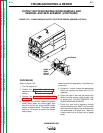
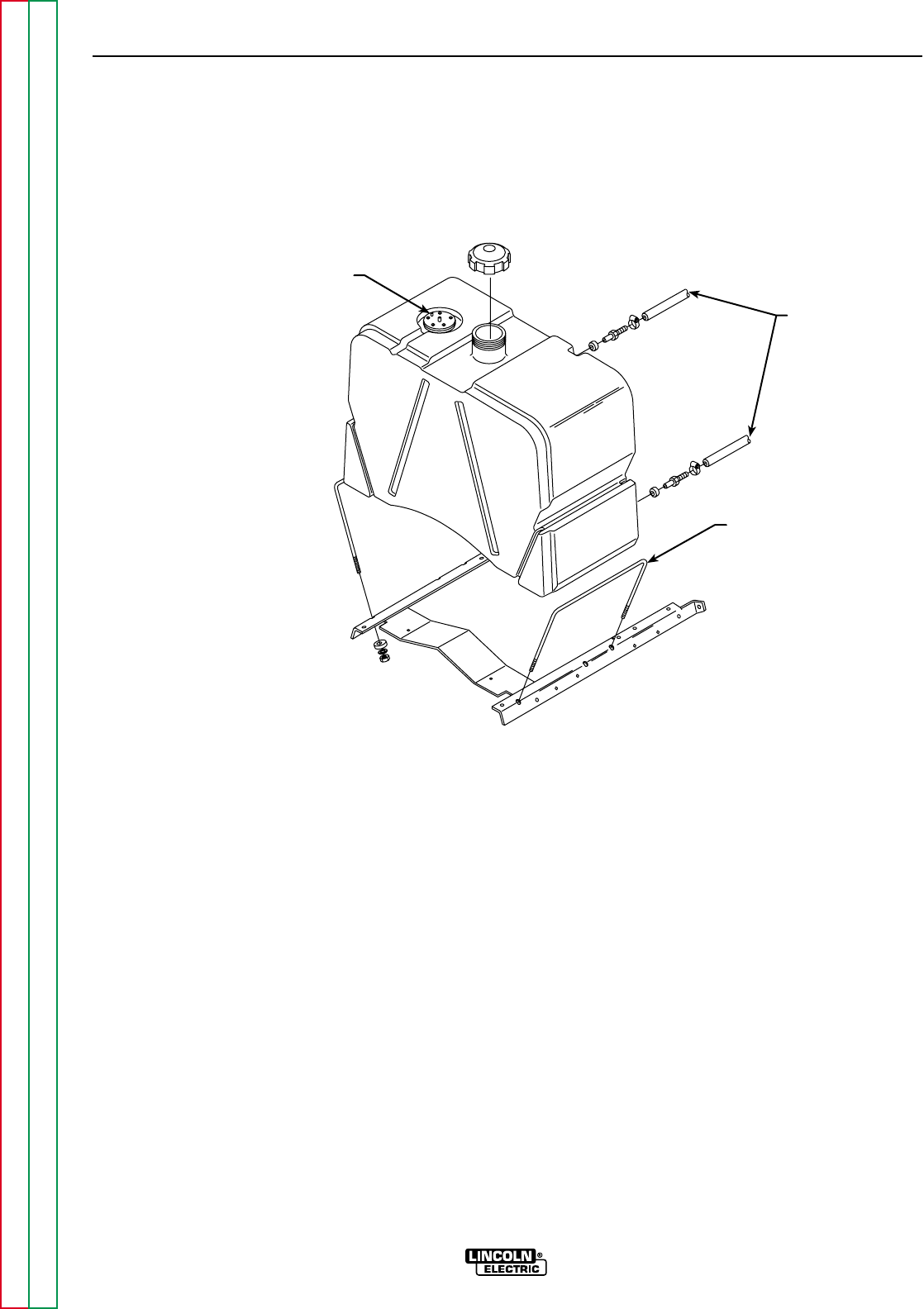
PLUG
FUEL
LINES
U-BOLTS (2)
LEADS #229
AND #242D
{
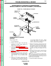
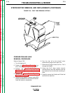
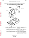
FIGURE F.33 – FUEL TANK REMOVAL DETAILS
STATOR/ROTOR REMOVAL AND REPLACEMENT (CONTINUED)
PREPARATION AND LEAD
REMOVAL PROCEDURE
Refer to Figure F.33.
1. Turn the engine off.
2. Perform the Case Cover Removal proce-
dure, including removing the output panel.
3. Perform the Power Module/Output
Rectifier Bridge Assembly Removal
Procedure.
4. Perform the Power Module Capacitor
Discharge Procedure.
5. Using the 3/8" wrench, remove leads #229
(white) and #242D from the fuel level sensor.
Label the leads for reassembly.
6. Turn the fuel off at the shutoff valve.
Remove and plug the fuel return line.
7. Remove and plug the lower fuel line. Pull it
through the firewall.
8. Using the 9/16" deep socket wrench,
remove the four lock nuts, washers, and rub-
ber washers from the fuel tank mounting U-
bolts.
9. Carefully remove the U-bolts and lift the fuel
tank from the machine.