


Idler Operational Exceptions
When the WELDING TERMINALS switch is in the
“Welding Terminals Remotely Controlled” position, the
idler will operate as follows:
a. When the triggering device (Amptrol, Arc Start
Switch, etc.) is pressed, the engine will accelerate
and operate at full speed provided a welding load
is applied within approximately 15 seconds.
• If the triggering device remains pressed but no
welding load is applied within approximately 15
seconds, the engine will return to low idle speed.
• If the triggering device is released or welding
ceases, the engine will return to low idle speed
after approximately 15 seconds.
8. HOUR METER
The hour meter displays the total time that the engine
has been running. This meter is a useful indicator for
scheduling preventive maintenance.
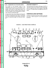
WELDER CONTROLS (Items 9 through 13 )
9. WELD MODE & OUTPUT CONTROL
These two controls allow you to select between various
welding output slopes and adjust the desired welding
output. Refer to Table B.1 for a description of how
these two controls work.
10. DIGITAL OUTPUT METERS
The digital output meters are located in the center of
the control panel between the two large control knobs.
The meters allow the output current level to be set prior
to welding in stick mode, and voltage level to be set
prior to welding in the wire modes. During the welding
process the meters display the actual output current
and voltage, within ±5% accuracy.
The digital meters allow the output voltage (CV-WIRE
mode) or current (CC-STICK, PIPE and TIG modes) to
be set prior to welding using the OUTPUT control dial.
During welding, the meters display the actual output
voltage (VOLTS) and current (AMPS). A memory fea-
ture holds the display of both meters on for seven sec-
onds after the welding is stopped. This allows the oper-
ator to read the actual current and voltage just prior to
when welding was ceased. While the display is being
held the left-most decimal point in each display will be
flashing. The accuracy of the meters is +/- 3%.
11. WELDING TERMINALS SWITCH
The toggle switch on the control panel labeled WELD
TERMINALS ON and REMOTELY CONTROLLED is
used to control the operation of the “solid state contac-
tor.” The switch allows for the selection of “Hot” or
“Cold” welding terminals.
With the switch in the WELD TERMINALS ON position,
the contactor is closed and the welding terminals are
always “Hot.”
With the switch in the REMOTELY CONTROLLED
position, the contactor operation is controlled by an
Amptrol, Arc Start Switch or some other type of trig-
gering device through the use of a control cable con-
nected to the 14-pin amphenol.
When the triggering device is pressed, the contactor is
closed and the welding terminals are “Hot.”
When the triggering device is released, the contactor is
opened and the welding terminals are “Cold.”
NOTE: The new Chopper Technology control circuitry
automatically senses when a remote output control pot
is plugged into either amphenol. Therefore, there is no
need for a local / remote switch.
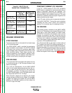
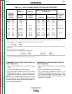
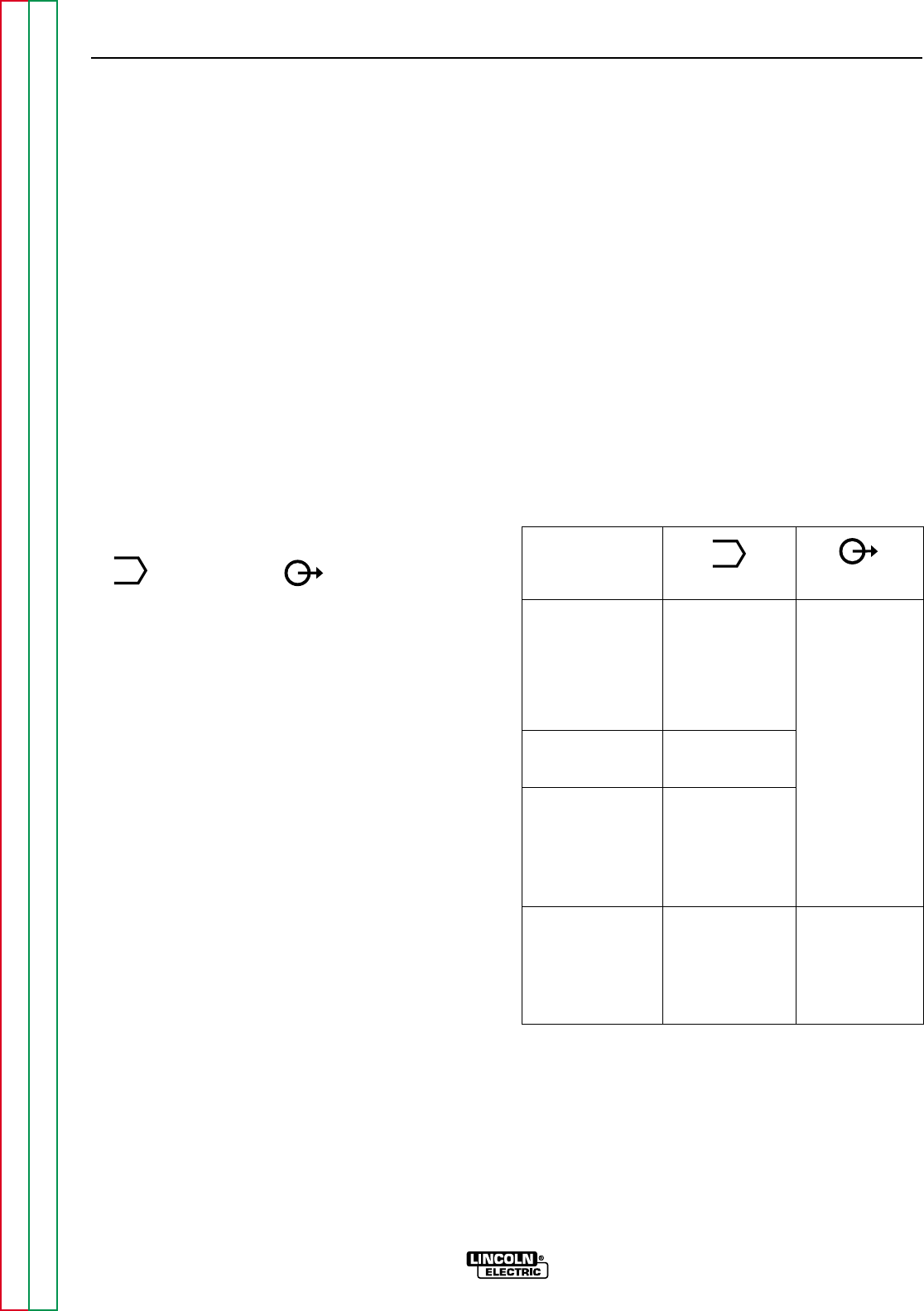
TABLE B.1 – WELD MODE AND OUTPUT
CONTROL FUNCTIONS
Application Weld Mode
1
Output
2
Sloped Output 5 Range
for Pipe Settings
Welding 90, 150, 200,
350, 500 (max. Provides a Fine
current on each Adjustment of
setting) Welding Current
from
Touch Start TIG 1 Range Setting Min (1) to Max
Welding 15-200 Amps (10) within each
range
Constant Current 1 Range Setting
Output for 20-250 Amps
Fabrication and
General Purpose
Welding
Constant Voltage 1 Range Setting Provides Fine
Output for MIG 14 to 40 Volts Voltage
WIRE or Adjustment
CORED WIRE
Welding
1
If the WELD MODE switch is positioned between settings, the pre-
vious setting is maintained until the switch is properly positioned on
a setting.
2
OUTPUT also controls O.C.V. while in the 5 sloped output ranges.
B-6 B-6
OPERATION
COMMANDER 500
Return to Section TOC Return to Section TOC Return to Section TOC Return to Section TOC
Return to Master TOC Return to Master TOC Return to Master TOC Return to Master TOC
M
M