


TROUBLESHOOTING & REPAIR
F-32 F-32
COMMANDER 500
Return to Section TOC Return to Section TOC Return to Section TOC Return to Section TOC
Return to Master TOC Return to Master TOC Return to Master TOC Return to Master TOC
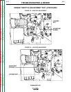
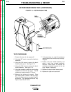
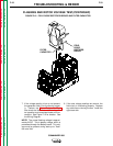
PLUG P/J52
LEAD # 200A
LEAD # 201A
PLUG P/J52
1
2
3
4
5
6
7
8
9
10 11
12 13
14 15 16
FILTER
CAPACITOR
FIELD DIODE
RECTIFIER BRIDGE
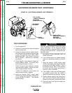
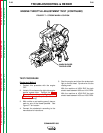
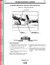
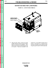
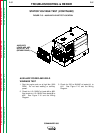
FIGURE F.11 – PLUG P/J52 LOCATION
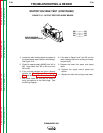
FLASHING AND ROTOR VOLTAGE TEST(CONTINUED)
TEST PROCEDURE
1. Using the 3/8" wrench, remove the sheet
metal screws from the right front case side.
2. Carefully remove the right case side.
3. Set the volt/ohmmeter to the DC volts
position.
4. Locate Plug P/J52 and leads #200A and
#201A. See Figure F.11.
NOTE: Cut any cable ties necessary to perform
the test. DO NOT UNPLUG PLUG P/J52.
5. Connect the positive meter probe to lead
#200A and the negative meter probe to lead
#201A.
6. Start the engine and run it at high idle speed
(1900 RPM). Check the voltage reading on
the meter. It should read approximately
16 VDC.