


TROUBLESHOOTING & REPAIR
F-44 F-44
COMMANDER 500
Return to Section TOC Return to Section TOC Return to Section TOC Return to Section TOC
Return to Master TOC Return to Master TOC Return to Master TOC Return to Master TOC
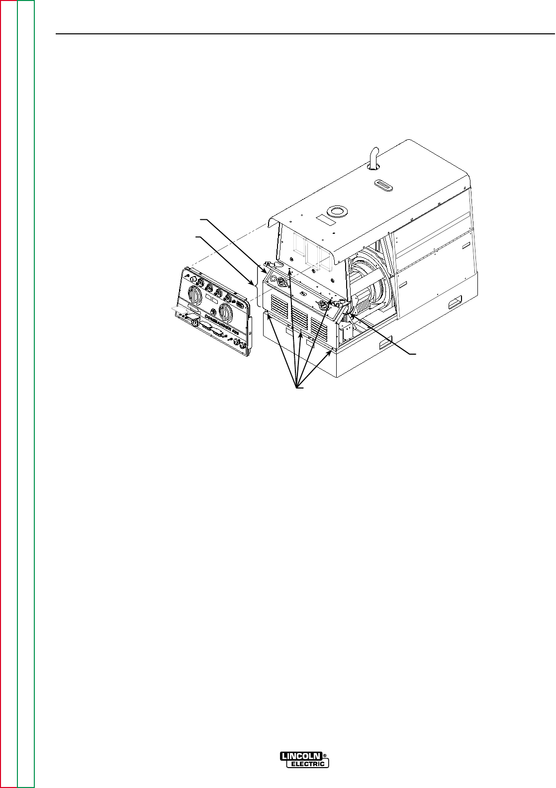
GREEN
GROUND
LEAD
OUTPUT PANEL
SCREWS
OUTPUT LEADS
(BEHIND PANEL)
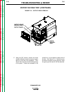
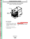
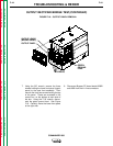
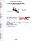
FIGURE F.19 – OUTPUT PANEL REMOVAL
OUTPUT RECTIFIER BRIDGE TEST(CONTINUED)
7. Using the 3/8" wrench, remove the three
screws holding the lower front panel (output
panel) to the case front assembly. Then
remove the front two screws holding the top
of the panel. These are accessed in the
control box, on the bottom at each side of
the box. Using the 7/16" wrench, discon-
nect the green ground lead. See Figure
F.19. Carefully move the lower front panel
to the right side.
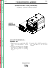
8. Disconnect Bypass PC board leads #206B
and #208 from their in-line connectors.