


TROUBLESHOOTING & REPAIR
F-63 F-63
COMMANDER 500
Return to Section TOC Return to Section TOC Return to Section TOC Return to Section TOC
Return to Master TOC Return to Master TOC Return to Master TOC Return to Master TOC
REMOVE LEADS
POWER
MODULE
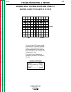
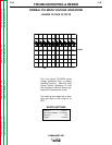
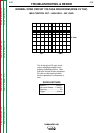
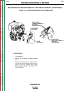
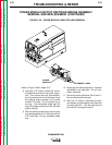
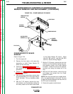
FIGURE F. 28 – POWER MODULE CAPACITOR LEAD REMOVAL
POWER MODULE/OUTPUT RECTIFIER BRIDGE ASSEMBLY
REMOVAL AND REPLACEMENT (CONTINUED)
Refer to Figure F.28 for Steps 8-12.
8. Using the 7/16" wrench, loosen the nuts on
the positive terminals of the power capaci-
tors. Then remove the nuts, lock washers,
and flat washers from the terminals where
the positive straps connect to the power
module PC board. Flip the straps out of
the way. Also disconnect diode lead D3
(right side power module) and D4 (left side
power module).
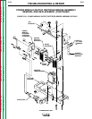
9. With the phillips screw driver, remove plug
and lead assembly for P/J 50 (right side) or
P/J51 (left side). Cut any necessary cable
ties.
10. Disconnect the thermostat leads. Separate
lead #249 on the right side. Cut any nec-
essary cable ties.
11. Disconnect leads #14A and 13A at their in-
line connectors (left side only).
12. With the 1/2" wrench, disconnect the bolt,
lock washer and flat washer from the shunt
at choke lead W11. Cut the cable tie and
pull lead W11 through the toroid.